Lab 1 - ECE 421L 

Authored by Edgar Rodriguez Nevares,

Email: rodrie27@unlv.nevada.edu

August 30, 2023


Pre-lab work


Lab description

This first lab will go through the first part of Tutorial 1 seen here

Use an Xterm (written and video) as discussed.

Lab Work: Tutorial 1


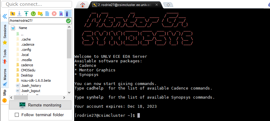
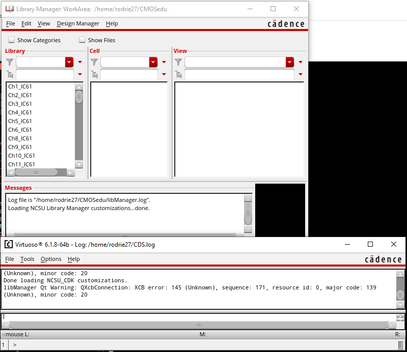
After setting up all the necesary files and setting up Cadence through MobaXterm we are able the start using Cadence’s Virtuoso editing tool. 

In the MobaXterm login 

  png1
   
typing "cd CMOSedu" in the command line
this changes the directory from home to CMOSedu

png2

 
By typing "virtuoso &" in the command liune opens up the program Cadence

png3

 
Creating a new library by going to the Library Manager clicking on File -> New -> Library
The library is name "Tutorial_1," and under Technology Library "AMI 0.60u C5N (3M,2P, high-res)" is chosen

png4


"Tutorial_1" is then Defined within the file cds.lib

 png5


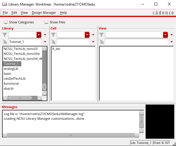
The "Tutorial_1" library in the Library Manager and then the menu items File -> New -> Cell View

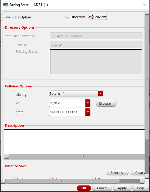
the cell is name "R_div"

png6


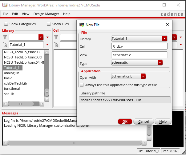
 The created cell "R_div" is created with the library "Tutorial_1"

png7


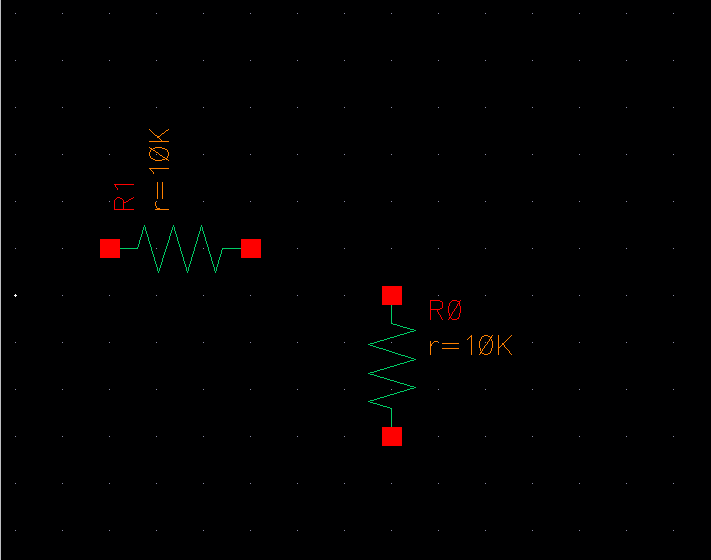
Either by the "create" tab and then clicking on instance, or pressing the bindkey "I" on the keyboard

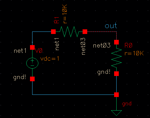
Resistors are chosen and set to 10k ohms

png8

 
Ground is created by creating another Instance

png9


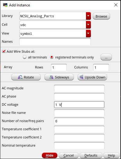
Voltage source is created by using the bindkey "I" and within the DC Voltage space it is set to 1 Volt

png10


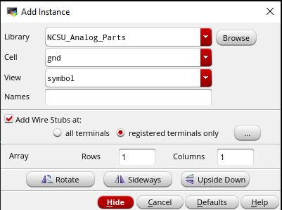
The circuit is completed after pressing the wire bindkey "w" and connecing the voltage source, resistors, and ground.

png11


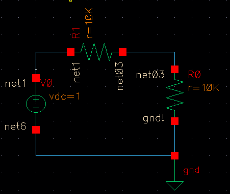
Afterwards, the "check and save" icon on the schematic is clicked

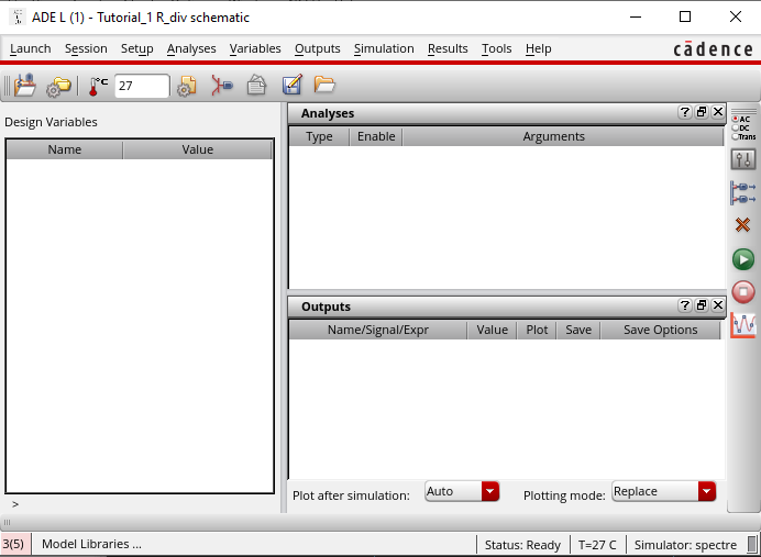
Then within to simulate Spectre, the Spice simulator within Cadence, the Launch tab is clicked and "ADE L" is selected

png12


The simulator type is set to "Spectre" by clicking on the "Setup" tab

png13


Analysis is set as "tran" within the "Analysis" tab

png14


Clicking on the Outputs -> To be plotted -> Select on Schematic the input and output voltage are chosen
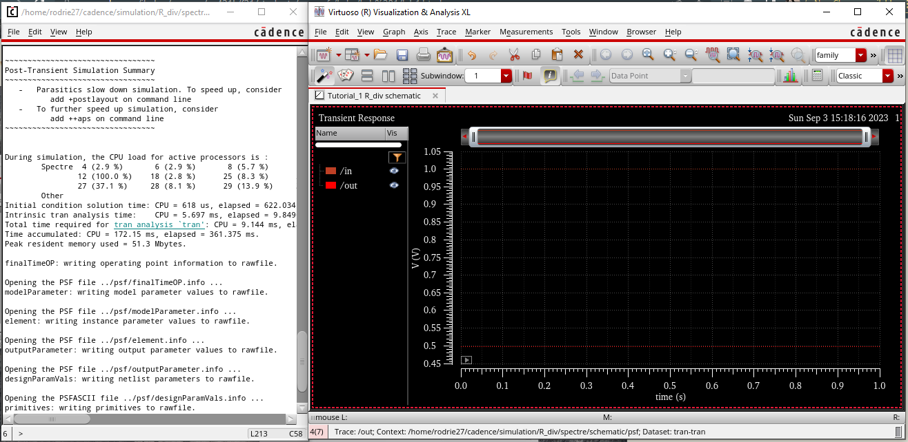
png15


 The 
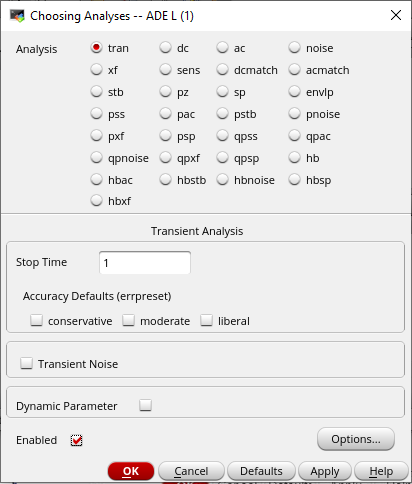
selected voltages to be plotted are listed below with the analysis type. After pushing the green "Net list and run" button the right-hand side in the ADE window.

png16


The state of the schematic is saved in the ADE window menu items by clicking Session -> Save State and select Cellview then OK

png17


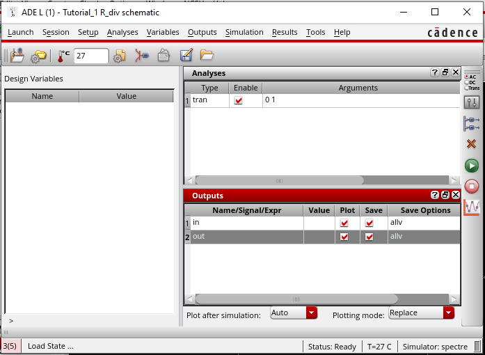
The circuit is then simulated and the voltages of Vin and Vout are plotted

png18


I created a back-up of the lab and saved it as a zip file

png19


A made a second back-up of the files by sending it to myself in my email

png20


return to labs