Lab 1 - EE 421L 

Authored by Damian Aceves-Franco,

acevesfr@unlv.nevada.edu

Due 09/01/2021


Pre-lab work


Lab description

This first lab will go through the first part of Tutorial 1 seen here

Use an Xterm (written and video) as discussed.

Lab Work: Tutorial 1


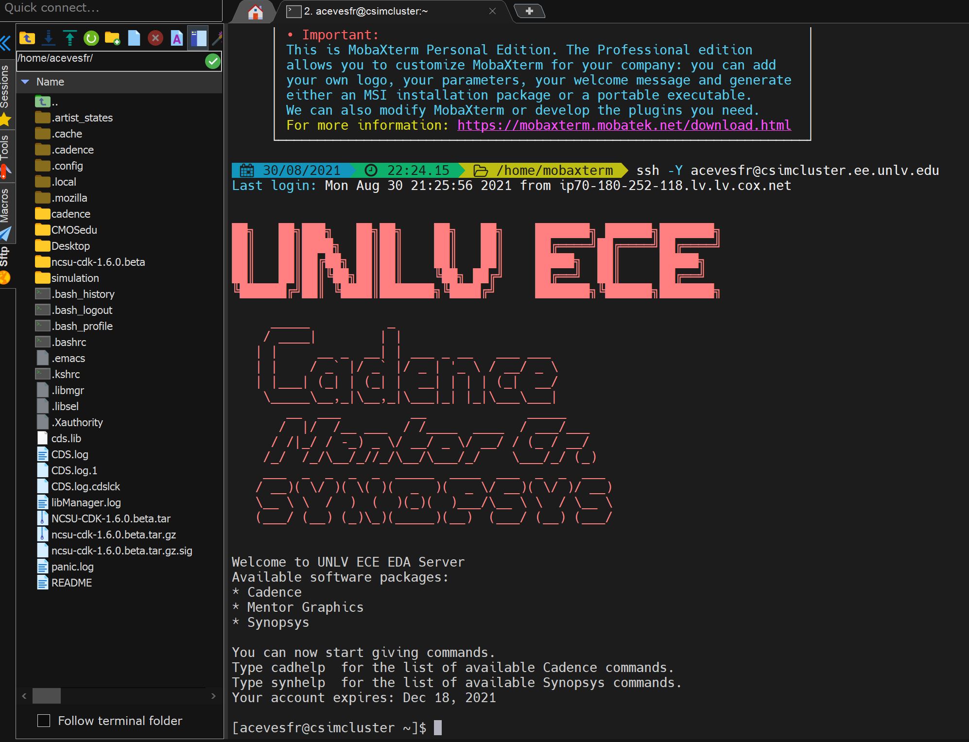
After setting up all the necesary files and setting up Canence through MobaXterm we are able the start using Cadence’s Virtuoso editing tool. 

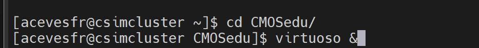
In the MobaXterm login 


   http://cmosedu.com/jbaker/courses/ee421L/f21/students/acevesfr/Labs/Lab%201/step%201.JPG

then type "cd CMOSedu/" press enter, next type "virtuoso &" press enter


http://cmosedu.com/jbaker/courses/ee421L/f21/students/acevesfr/Labs/Lab%201/step%202.JPG


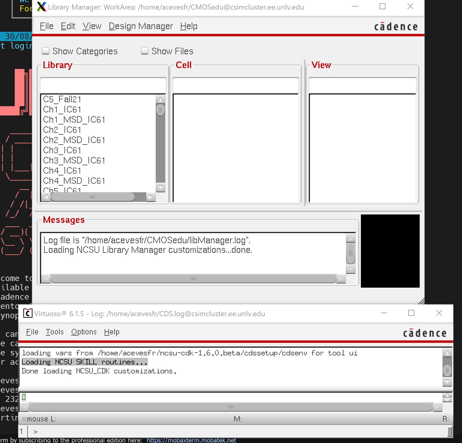
Next when starting Virtuoso the window below with appear

   http://cmosedu.com/jbaker/courses/ee421L/f21/students/acevesfr/Labs/Lab%201/step%203.JPG


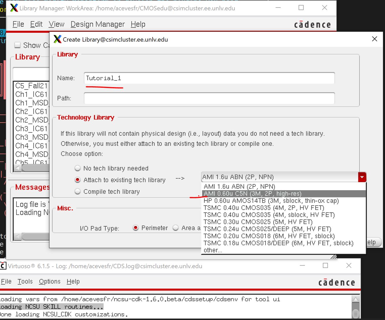
Then we creat a library by, Library Manager, File -> New -> Library. Name it Tutorial_1 and attach the AMI 0.06u C5N 


http://cmosedu.com/jbaker/courses/ee421L/f21/students/acevesfr/Labs/Lab%201/step%204.JPG


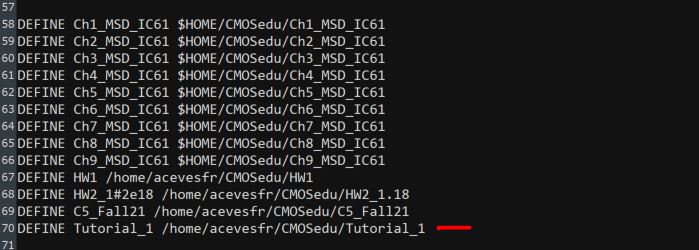
We must then make sure the the new library was added to the cds.lib file. Normialy it is done automaticly.

       
http://cmosedu.com/jbaker/courses/ee421L/f21/students/acevesfr/Labs/Lab%201/step%205.JPG


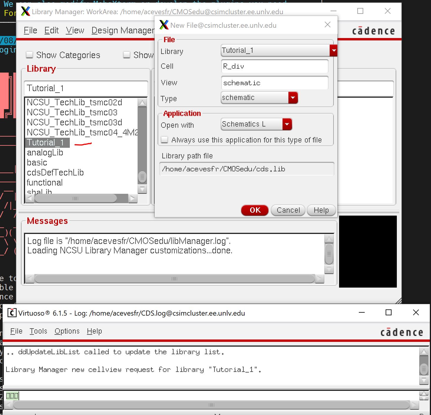
Next lets go through the Library Tap and look for the Tutorial_1 and make a cell for it so menu items File -> New -> Cell View and enter the information seen below and press OK


http://cmosedu.com/jbaker/courses/ee421L/f21/students/acevesfr/Labs/Lab%201/step%206.JPG


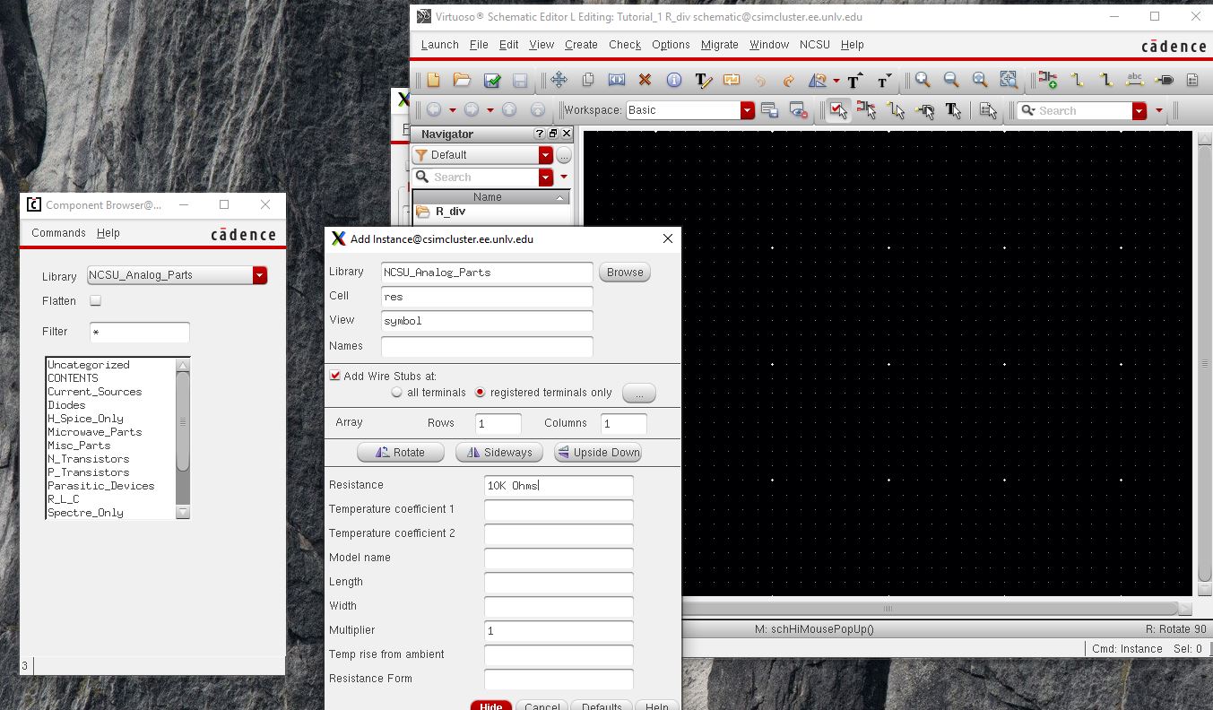
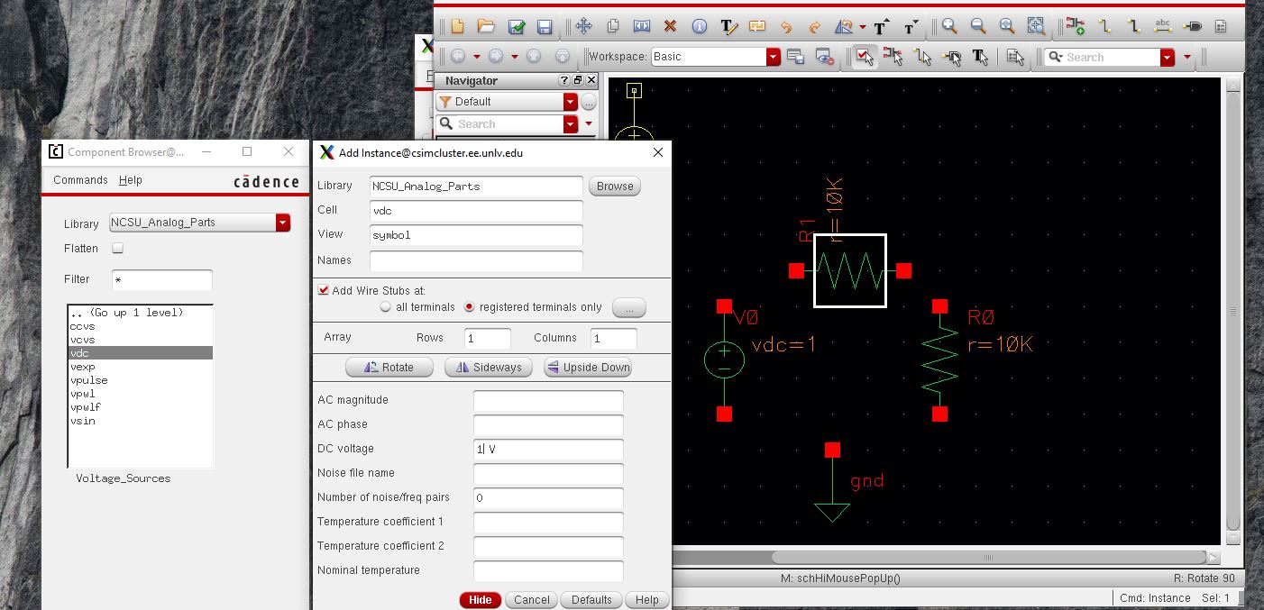
Next let place a component on the schematic, so we go to Creat-> Instance. A window called Component Brower will popup with a Add Instance  window. In the 

Component Brower find the Library NCUS_Analog_parts. when look for R_L_C press that end it will lead you to the "res" press that and set the value of the

resistor to 10K Ohms

           
http://cmosedu.com/jbaker/courses/ee421L/f21/students/acevesfr/Labs/Lab%201/step%207.JPG
           

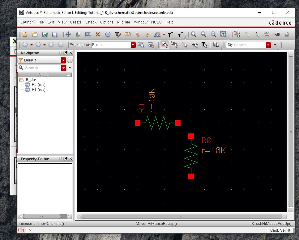
Place two resistors pressing R rotated the symbol and pressing Ecs leaves the "Add Instance" mode or any mode 

F key on the keyboard fits the viewing 


http://cmosedu.com/jbaker/courses/ee421L/f21/students/acevesfr/Labs/Lab%201/step%208.JPG


Then we place the groud the same way we did before. This will also apply to the volage sorce. 


http://cmosedu.com/jbaker/courses/ee421L/f21/students/acevesfr/Labs/Lab%201/step%209.JPG


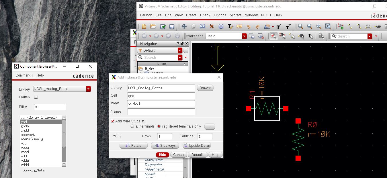
to find the voltage source go to Volage_Sources then "vdc"


http://cmosedu.com/jbaker/courses/ee421L/f21/students/acevesfr/Labs/Lab%201/step%2010.JPG


To connect the components just the wire key of press w for wire


http://cmosedu.com/jbaker/courses/ee421L/f21/students/acevesfr/Labs/Lab%201/step%2011.JPG


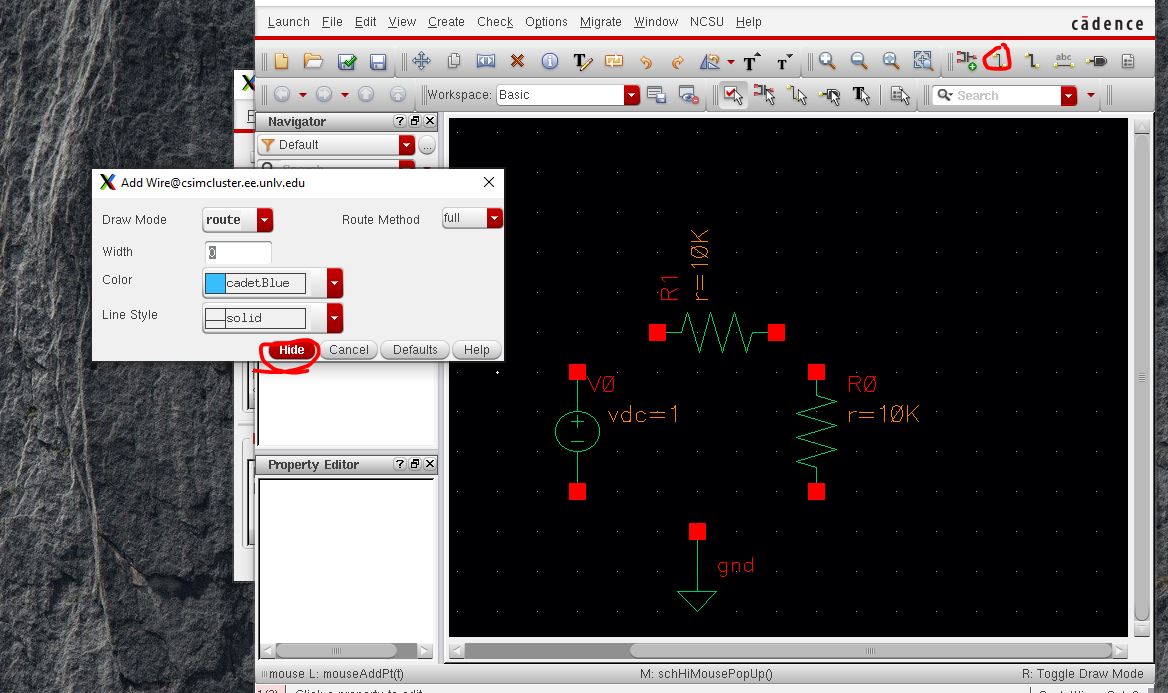
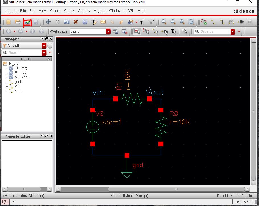
when done lets lable the wire using the "abc" key or use use lowercase L to label it


http://cmosedu.com/jbaker/courses/ee421L/f21/students/acevesfr/Labs/Lab%201/step%2012.JPG


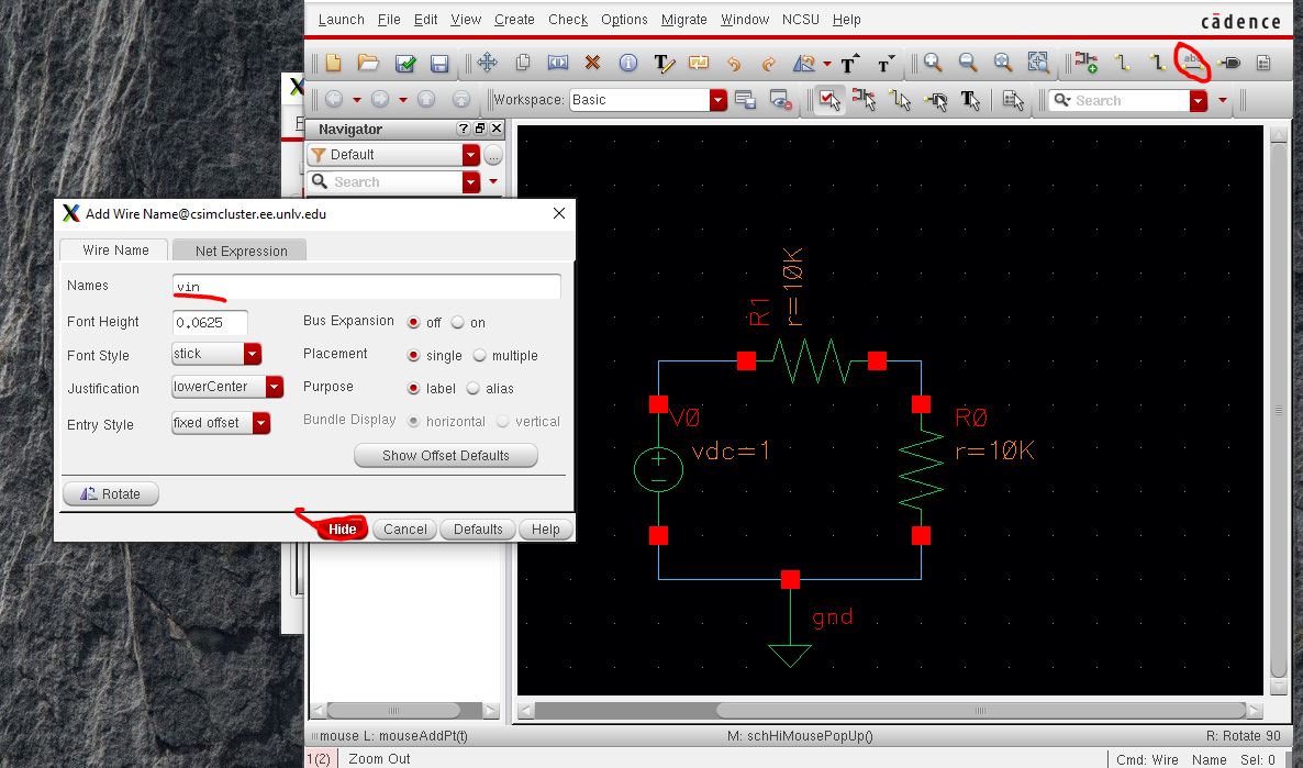
Now let press the "Check and Save"


http://cmosedu.com/jbaker/courses/ee421L/f21/students/acevesfr/Labs/Lab%201/step%2013.JPG


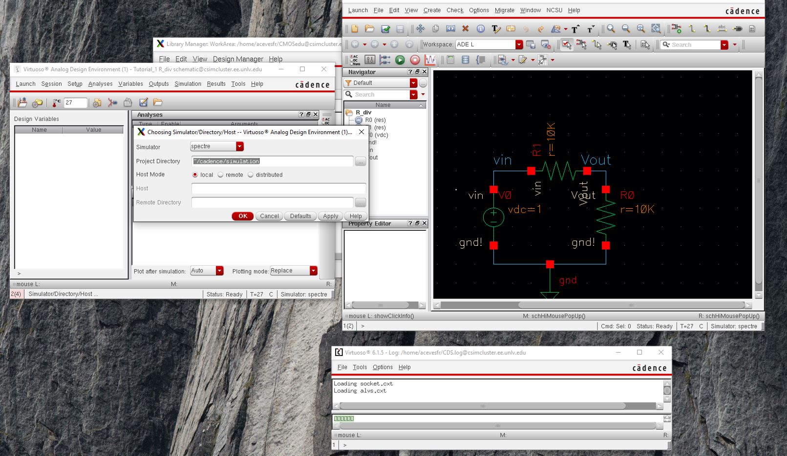
Now after the Check and Save  go to Lunch -> ADE L 

a window will popup called The Virtuoso Analog Design Environment and go to menu in the ADE and go to Setup -> Simulator set to Spectre

pess OK


http://cmosedu.com/jbaker/courses/ee421L/f21/students/acevesfr/Labs/Lab%201/step%2014.JPG


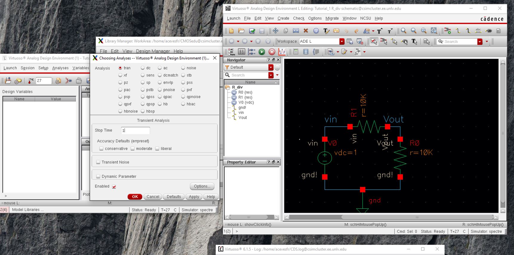
Next go to Analyses -> Choose and select a transient analysis (tran), a stop time of 1 second and it Enabled press OK

 http://cmosedu.com/jbaker/courses/ee421L/f21/students/acevesfr/Labs/Lab%201/step%2015.JPG


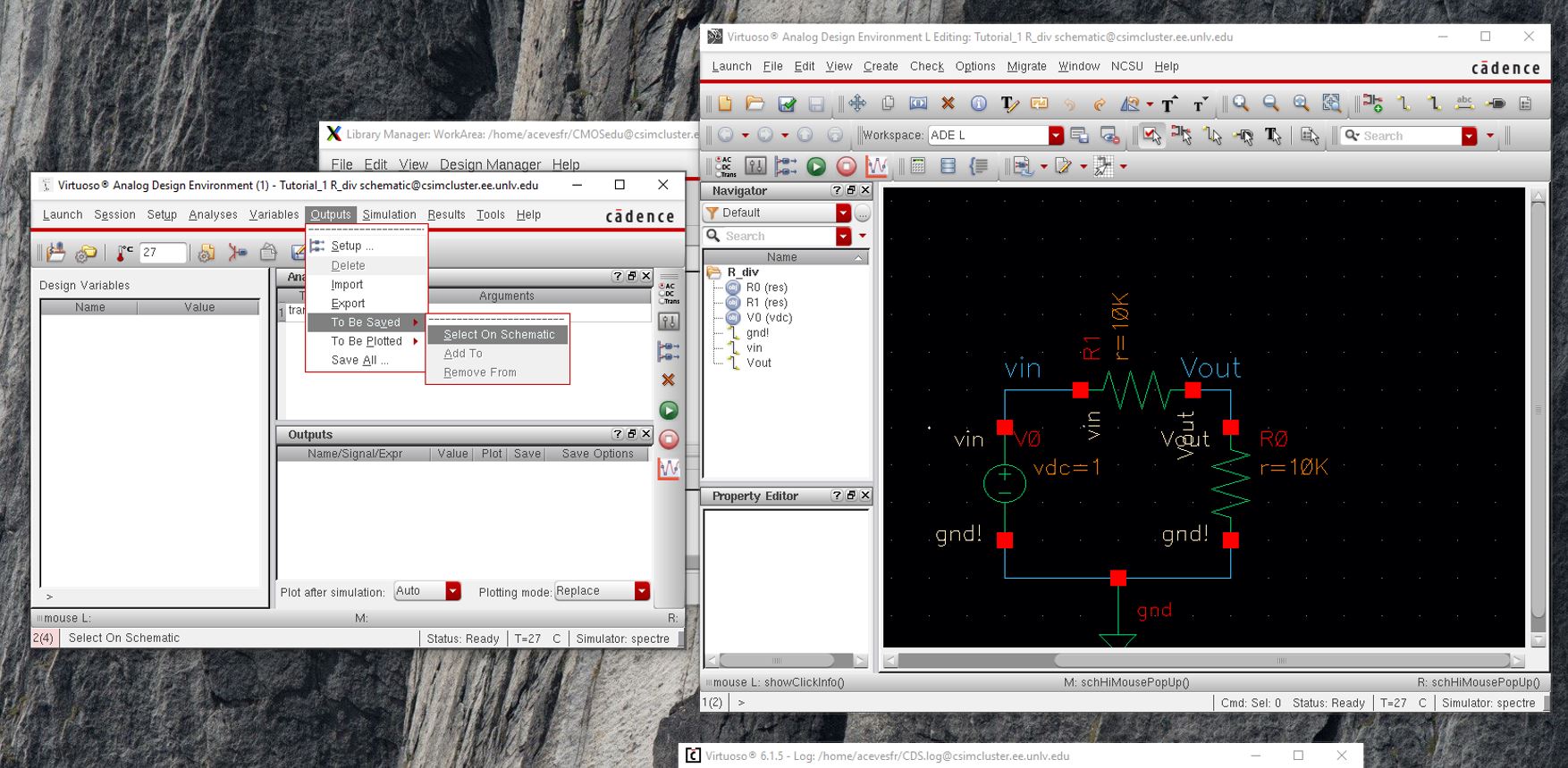
Then we need to select the signals we want to plot go to Outputs -> To Be Plotted -> Select On Schematic


http://cmosedu.com/jbaker/courses/ee421L/f21/students/acevesfr/Labs/Lab%201/step%2016.JPG


Go the Schematic and select the vin and Vout wires the will color up and they will appear on the ADE window


http://cmosedu.com/jbaker/courses/ee421L/f21/students/acevesfr/Labs/Lab%201/step%2017.JPG


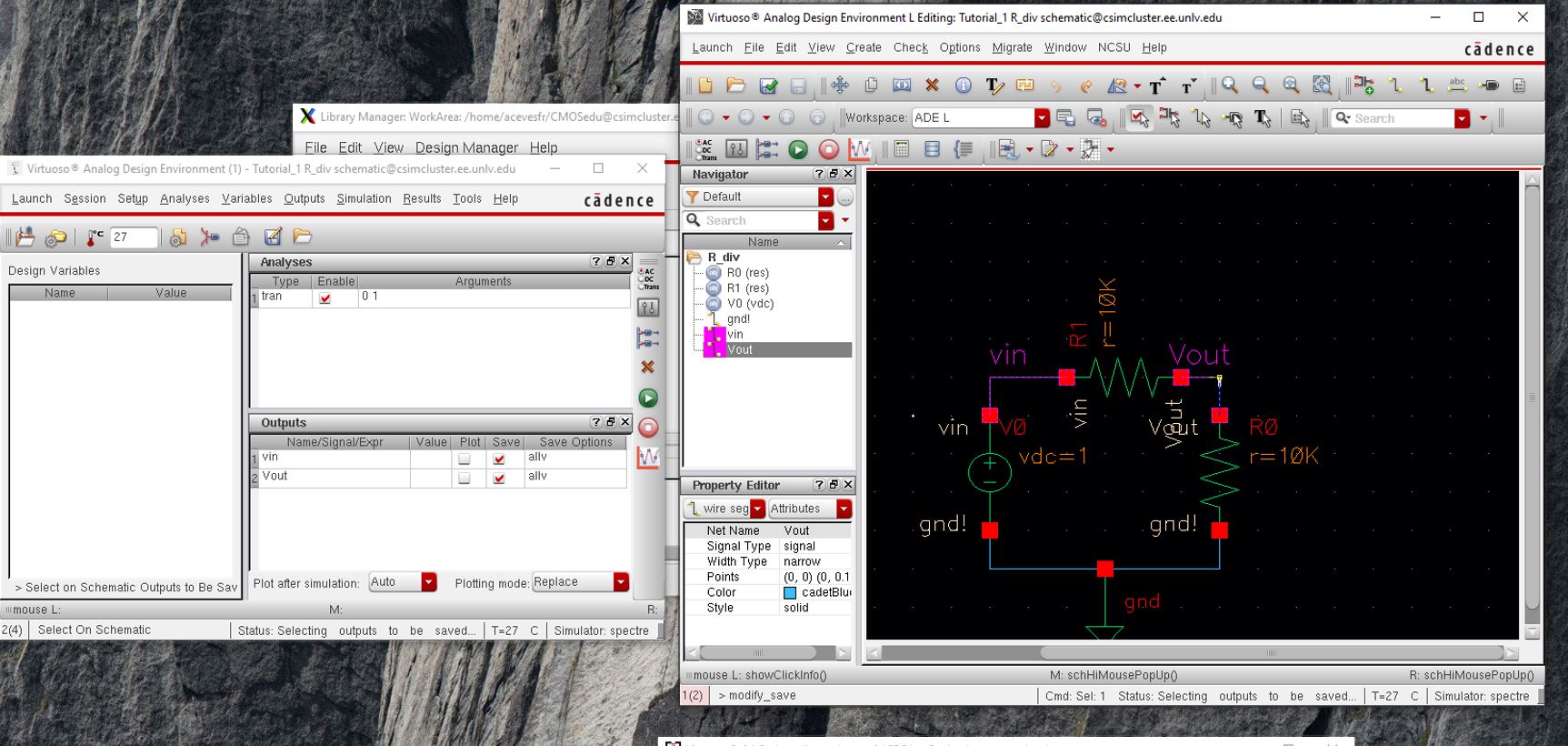
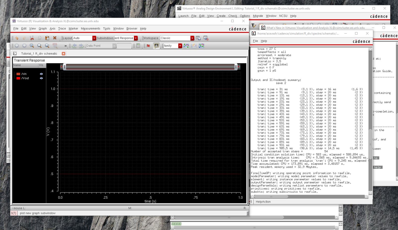
Now we are done and press the green button to simulate the circuit


http://cmosedu.com/jbaker/courses/ee421L/f21/students/acevesfr/Labs/Lab%201/step%2018.JPG


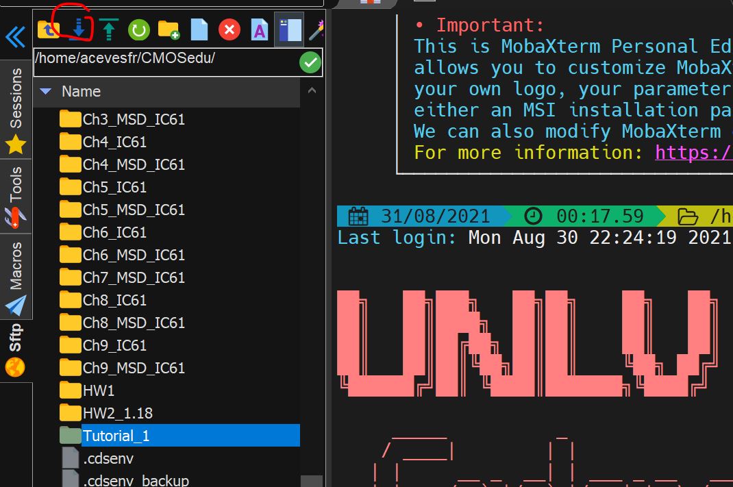
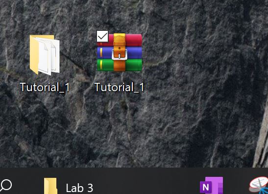
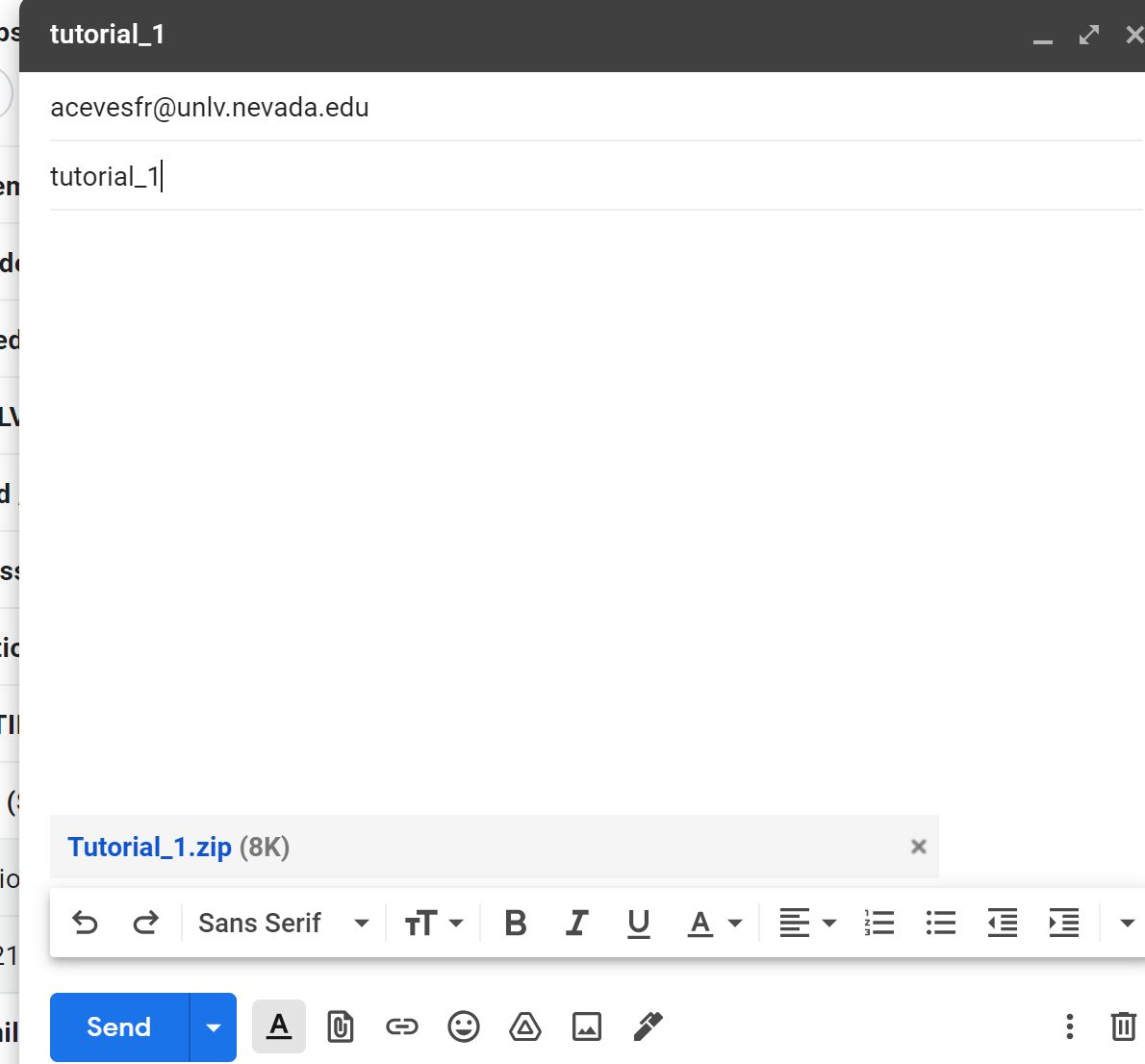
Now regular backups will be done by downloading the file from MoBaX and zipping it and emailing it to myself


http://cmosedu.com/jbaker/courses/ee421L/f21/students/acevesfr/Labs/Lab%201/step_1.JPG


http://cmosedu.com/jbaker/courses/ee421L/f21/students/acevesfr/Labs/Lab%201/step_2.JPG


http://cmosedu.com/jbaker/courses/ee421L/f21/students/acevesfr/Labs/Lab%201/step_3.JPG

http://cmosedu.com/jbaker/courses/ee421L/f21/students/acevesfr/Labs/Lab%201/step_4.JPG


 return to labs