Lab 1 - EE 421L Fall 2021
Authored
by: Anthony Torres
Email: torrea20@unlv.nevada.edu
Due Date: September 1, 2021
Lab Description
Laboratory introduction including generating/posting html reports and installing/using Cadence.
Pre-Lab
The prelab work is following a tutorial found here for editing webpages and it includes the following.
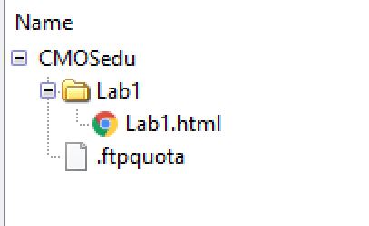
- Using Windows Expolorer to read and write from the CMOSedu server
- Creating a file and including a lab document as well as pictures
- Using Komposter to edit those file and upload to CMOSedu Server as shown by the followin snip
Main Lab
The first lab goes through Tutorial 1
up to the 25th image of the tutorial. The Tutorial shows how to
install directories on Cadence as well as CMOSedu book examples while
providing an example of creating a library and creating and simulation
circuit in that library. A brief structure of the report is shown
below.
- Cadence running correctly
- Creating a library and defining that libarary
- Creating a voltage divider schematic
- Setting up the correct simulation
- Simulation results
- How work was saved
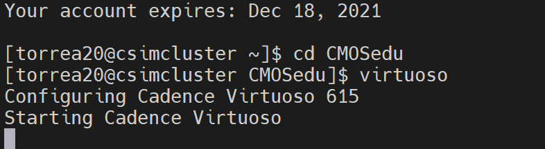
The
first part of the Tutorial is making sure the directories are including
into the home account called CMOSedu and ensuring that the user is able
to connect to Cadence via the virtuose & command.
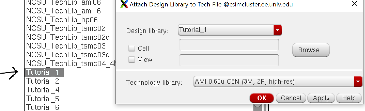
The next part of is the creation of the library in this case it is named Tutorial_1 and this is done simply by the following (File - New - Lbrary).
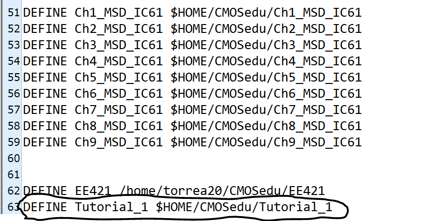
Once
this library is created it needs to be defined in the cds.lib file as
shown below. If the library is named differntly simplify replace
Tutorial_1 with the library name.
Once
the library was created a cell was created by (File - New - Cell View)
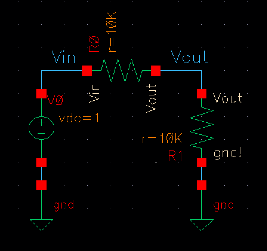
and was set as a schematic. The voltage divider below was created
in that cell.
- First I needed to go to "Create" then "Instance"
- After that the components needed were under the NCSU_Analog_Parts library
- Once the library was acces the components needed were included and given values
- The last part was wiring them together using "W" key and naming the nodes
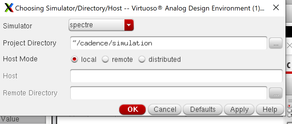
Once the schematic was completed the simulation needed to be setup.
- First "Save and Check" was pressed to ensure no errors
- Next Launch and ADE L was selected
- Once there spectre need to be chosen as the directory host
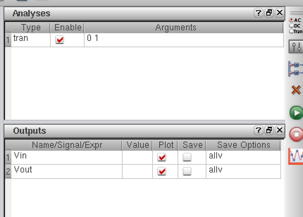
The next part of the simulation includes choosing which response will be chosen in this case trans which was done by hitting Analyses
- Trans. After this was done Outputs - To Be Plotted - Select on
Schematic was hit. This allows the user to go to the schematic and
choose which nodes are to be check in this case Vin and Vout are
checked.
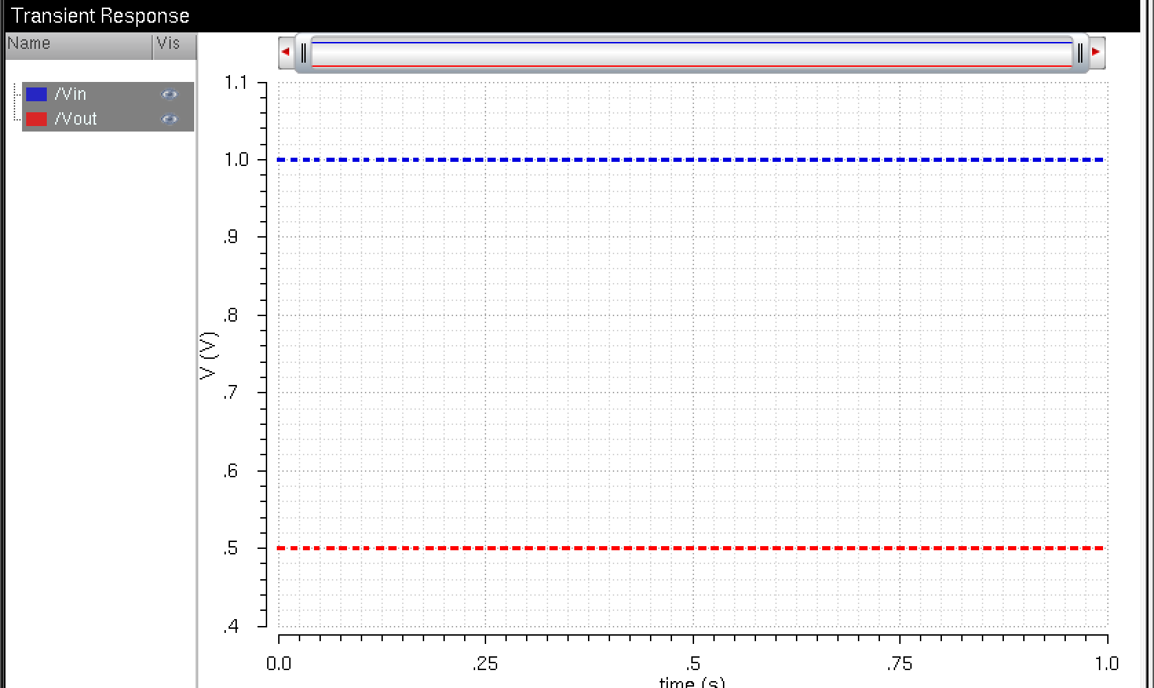
After everything is setup the green run button may be hit and the response will show up in another window. As shown below Vin and Vout of the voltage divider are given by the graph.
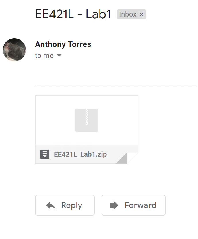
The
Final part of the lab is showing that my work is backed up. In
this case I first downloaded my Tutorial_1 from MobaXTerm and included
it in a file with my pictures and html file and then zipped them
together. Once that was done I emailed them to a secondary email
account so that I may not lose my work.
Return to Student Lab Reports
Return to Class Webpage