EE 421L
Digital
Integrated Circuit Design Laboratory
Laboratory
Report 6: Design, Layout, and Simulation of a CMOS NAND Gate, XOR Gate, and
Full-Adder
AUTHOR:
Bryan Kerstetter
EMAIL:
kerstett@unlv.nevada.edu
OCTOBER
23, 2019
General
Overview
The goal of this laboratory
is to design, layout, and simulate a CMOS NAND and XOR gates. Ultimately, these
gates will used to create a CMOS full adder. This is truly the first true circuit
design implemented in this laboratory.
Prelab
This laboratory prelab
regards Dr.
Baker’s fourth Cadence tutorial on CMOSedu.
A NAND schematic was
drafted.

Figure 1
The symbol created for our NAND gate.

Figure 2
A simple circuit created to ensure that the NAND gate
functions properly.

Figure 3
The NAND gate is confirmed to work based upon the following simulation results.

Figure 4
Layout of the NAND gate.

Figure 5
NAND gate layout passes DRC and LVS.

Figure 6
The netlists match, but do
the device sizes match?

Figure 7
Ensure that FET parameters (including device sizes)
are compared.

Figure 8
Run LVS, under newly
specified LVS Rules that considers FET parameters.

Figure 9
Looking at the LVS output,
we see the issue. Therefore, we may fix this issue by adjusting the layout
MOSFET parameters.

Figure 10
The
MOSFET geometries in the layout were modified such that the layout is
consistent with the schematic.

Figure 11
Now finally, the layout agrees
with the schematic, while considering the actual device sizes.

Figure 12
Laboratory
Procedure
Introduction
This laboratory regards
designing, laying out, and simulating a CMOS full adder. A full adder topology
is given below with the following schematic (Figure 13). The given full adder
topology consists of three NAND gates and two XOR gates. All NMOSs and PMOSs in
this full adder design will have a geometry of 6µm/0.6µm. All devices are
designed with a 27µm standard cell frame. The truth table of a full adder can
be seen in Table 1.

Figure 13
Table 1
|
A |
B |
Cin |
S |
Out |
|
0 |
0 |
0 |
0 |
0 |
|
0 |
0 |
1 |
1 |
0 |
|
0 |
1 |
0 |
1 |
0 |
|
0 |
1 |
1 |
0 |
1 |
|
1 |
0 |
0 |
1 |
0 |
|
1 |
0 |
1 |
0 |
1 |
|
1 |
1 |
0 |
0 |
1 |
|
1 |
1 |
1 |
1 |
1 |
The design and layout of a full adder consists of the
following design portions:
1. Design
and Layout of Inverter
2. Design
and Layout of NAND Gate
3. Design
and Layout of XOR Gate
1. Design
and Layout if Inverter
Schematic of an inverter (refer to previous laboratory).

Figure 14
The symbol of the inverter.

Figure 15
Layout of inverter.

Figure 16
Extracted view of inverter.

Figure 17
Inverter passes both DRC and LVS.

Figure 18
2. Design
and Layout of NAND Gate
Schematic of the NAND gate (refer to prelab).

Figure 19
NAND gate symbol.

Figure 20
NAND gate layout.

Figure 21
Extracted view of NAND gate layout.

Figure 22
NAND gate layout passes both DRC and LVS.

Figure 23
3. Design
and Layout of XOR Gate
A schematic of the XOR gate was drafted.
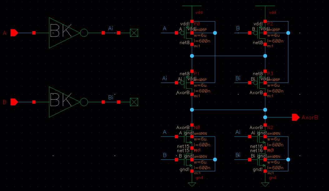
Figure 24
XOR Gate Symbol

Figure 25
XOR Gate Layout

Figure 26
The extracted view of the XOR gate layout.

Figure 27
The XOR gate passes both DRC and LVS.

Figure 28
Simulation of the Inverter, NAND, and XOR
Gates
A circuit was drafted to simulate the NOT gate, NAND
gate, and XOR, gate.

Figure 29
Schematic Simulation

Figure 30
Extracted Simulation

Figure 31
Summary of Simulation results.
Inverter Truth Table
Table 2
|
A |
Ai |
|
0 |
1 |
|
1 |
0 |
NAND Truth Table
Table 3
|
A |
AnandB |
|
|
0 |
0 |
1 |
|
0 |
1 |
1 |
|
1 |
0 |
1 |
|
1 |
1 |
0 |
XOR Truth Table
Table 4
|
B |
A |
AorB |
|
0 |
0 |
0 |
|
0 |
1 |
1 |
|
1 |
0 |
1 |
|
1 |
1 |
0 |
The CMOS inverter, NAND gate, and XOR gate is
confirmed to work (according to Figures 30-31 & Tables 2-4). Upon looking
at Figure 30 and 31, it becomes evident that during the transitory stages of
the edges the outputs are indecisive in a value causing the dips that are highlighted
in yellow. In the endnote, the effects of transitory edges will be reduced.
Design, Layout and Simulation of a Full
Adder
Design
A schematic based upon the topology of a full added in
Figure 13 was drafted.

Figure 32
Symbol of full adder.

Figure 33
Layout of Full Adder
A layout representing the designed full adder circuit
was designed.

Figure 34
Extracted view of the full adder layout.

Figure 35
The full adder layout passes both the DRC and layout.

Figure 36
A schematic was created to test the full adder.

Figure 37
Schematic Simulation

Figure 38
Extracted
Simulation

Figure 39
Table 5
|
A |
B |
Cin |
S |
Out |
Confirmation in Waveform |
|
0 |
0 |
0 |
0 |
0 |
Confirmed |
|
0 |
0 |
1 |
1 |
0 |
Confirmed |
|
0 |
1 |
0 |
1 |
0 |
Confirmed |
|
0 |
1 |
1 |
0 |
1 |
Confirmed |
|
1 |
0 |
0 |
1 |
0 |
Confirmed |
|
1 |
0 |
1 |
0 |
1 |
Confirmed |
|
1 |
1 |
0 |
0 |
1 |
Confirmed |
|
1 |
1 |
1 |
1 |
1 |
Confiremd |
Based
upon Figures 38-39 and Table 5, the full adder is confirmed to work.
Endnote:
Using Buffers to Ensure Fast Edges!
Buffers
can be added to the inputs of the full adder to minimize issues caused by input
transitions. Exactly that is implemented in Figure 40. The simulation results are
seen in Figure 41.

Figure 40

Figure 41
Return to EE
421L Fall 2019 Page
Return to Dr. Baker’s CMOSedu homepage
