Lab 1 – Laboratory Intro, Installing and Using Cadence
EE 421L Digital IC Design
Lab Date: 8/28/19 Due: 9/04/19
Last Edited on
9/03/19 at 1:08pm using Word
In this lab,
we will be learning how to install Cadence and making a simple schematic and
simulating it in Virtuoso.
To be brief,
we will be following how to install Cadence using this guideline
provided by Dr. Baker.
To summarize
what I have done to install Cadence:
-
Request an account from Dr. Greg (assuming you are a UNLV Student)
and retrieve your username and password (usually given by email).
-
Download MobaXterm
o You can
download the latest version here
-
After launching MobaXterm, start new
local terminal and login to the ssh client.
-
Download the NCSU-CDK-1.6.0.beta.tar file from their website (the
site wanted my email address, so I gave it to them and got a email link).
-
Followed the rest of the instructions from Dr. Baker’s Guideline.
--------------------------------------------------------
Experiment 1: Layout and
simulation of a resistive voltage divider
For this
experiment, we will be following the Cadence Design Tutorials from CMOSedu.com
Most of the Cadence
setup has been done if you followed the guideline. The part that will need to
be added is deleting divaDRC.rul, divaEXT.rul,
and divaLVS.rul and following the tutorial from there
on.
After the
initial setup and running Virtuoso, lets build our
circuit.
Favorite bindkeys
are:
-
Key i (to create an electrical
component, or instance)
-
Key w (to create a wire)
-
Key f (to find where your circuit is, aka “Fit” the circuit to the
window)
-
Key q (so that we can change values of resistors)
-
Key l “Lowercase L” (So that we can label our circuit and make the
grader happy ^-^)
-
Key u (to undo an error, wont work if
you already saved it)
After reading
how to setup a tutorial library, attaching the AMI (On Semiconductor) 0.6μ
C5N process, defining the library (using DEFINE
Tutorial_1 $HOME/CMOSedu/Tutorial_1) in the
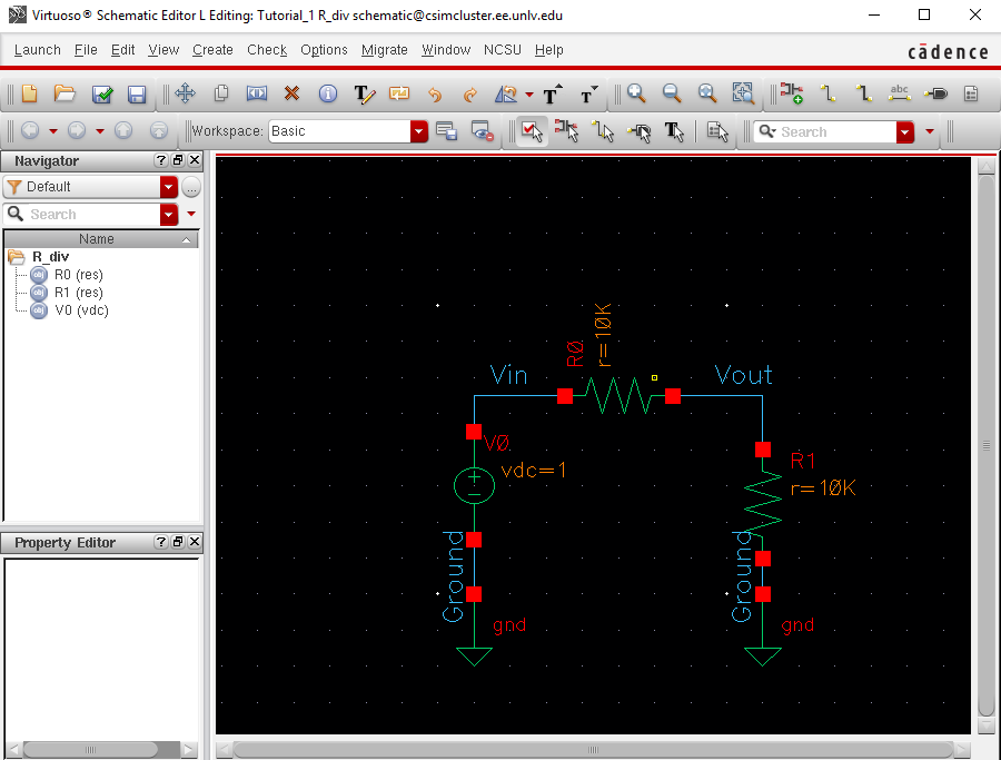
cds.lib file, and creating a new schematic (with parts already in place), this
is the result:
Clicking
“Check and Save” at the top left corner of the window and we get this:
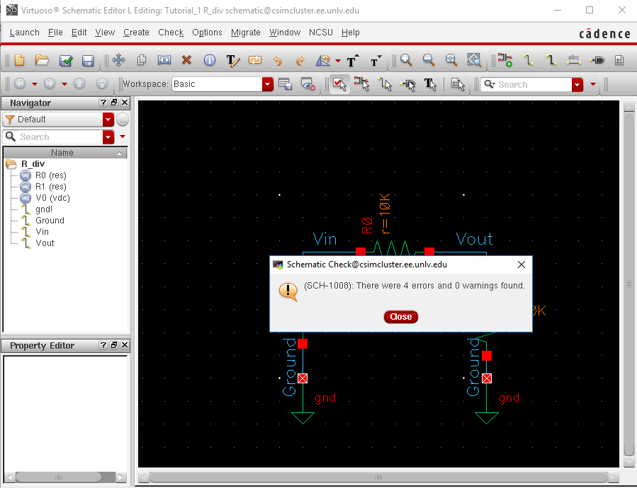
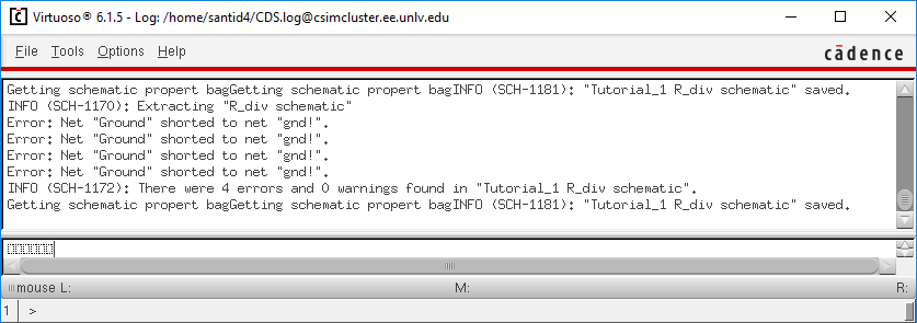
As we can see,
this window will be very handy in figuring out what problems we need to fix.
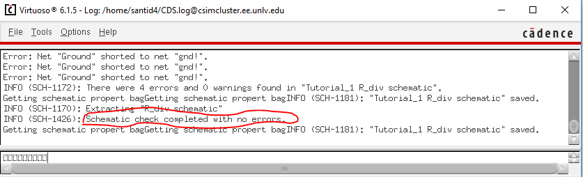
After fixing
the errors and doing “Check and Save” again:
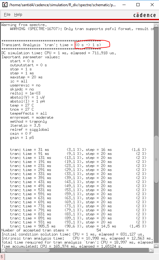
Following the
tutorial, launching the Virtuoso Analog Design Environment L, performing a
transient simulation of 1 second, and plotting Vin and Vout:
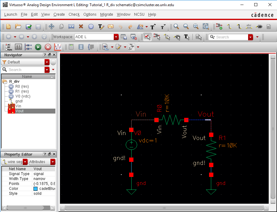
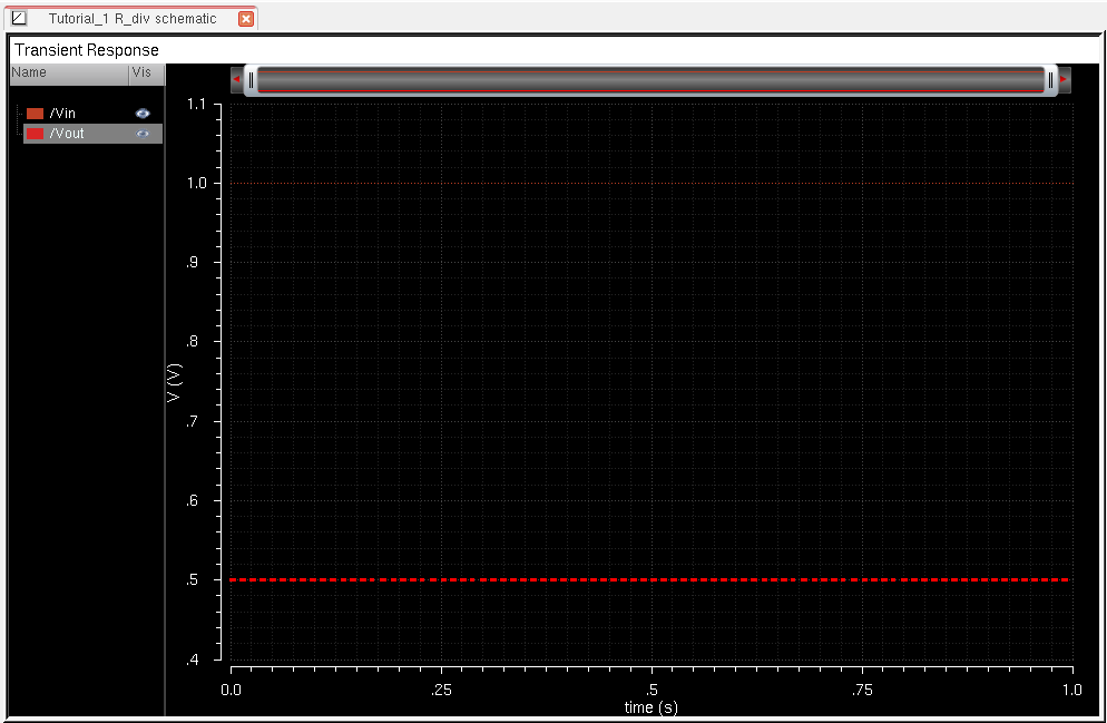
Looking at the
Waveforms, and doing a simple hand calculation for Vout,
we can say that the circuit has been successfully simulated.
------------------------------------------------------
Backing up work:
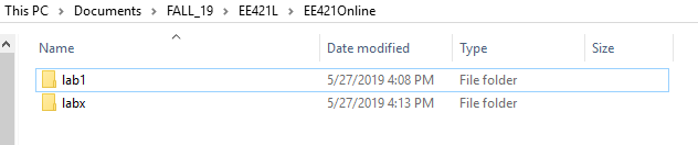
The way I will
be backing up my work will be simple:
-
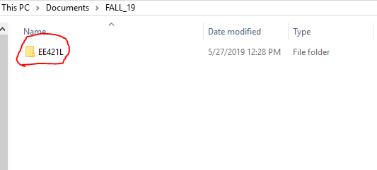
I will create an EE421L folder, with 2 sections: The online part
(which will contain all the .html files, pictures, and revised lab reports that
I will post onto my CMOSedu lab page) and an offline
part (which will contain any messy work, snips, or anything I do in general to
help write up the reports.
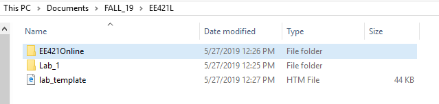
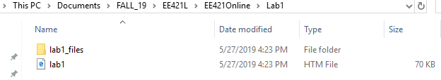
(Lab report labeled as “lab1.htm”)
All of the files shown will be saved onto my personal
laptop and into a USB. Every time a lab report is submitted, I go into my
“EE421Online” folder, and drag the lab folder into the ftp window that will
upload the folder onto my CMOSedu lab page.