Lab 1 - ECE 421L
Authored
by Jared Hayes - hayesj18@unlv.nevada.edu
August 31, 2015
Lab Description:
Learn how to generate/post html lab reports and how to install and use
Cadence. Then design and simulate a schematic of a resistive voltage divider in accordance to tutorial 1
(up to the 25th image) on the CMOSedu website. This lab report
assumes that one has already properly configured their Cadence
environment using this tutorial.
Lab Report:
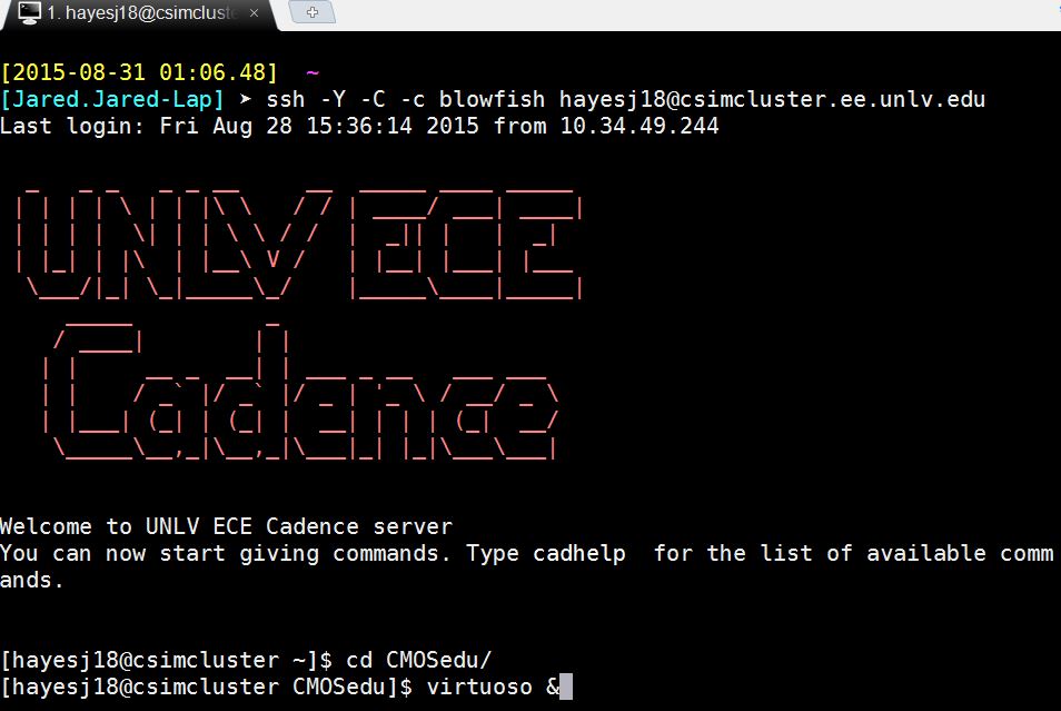
We will be using Mobaxterm to ssh into the cadence server with the following command:
	ssh -Y -C -c blowfish username@csimcluster.ee.unlv.edu

Change to the CMOSedu directory in order to run Cadence:

	cd CMOSedu

Start Cadence as a background process (& symbol) so that we can still issue commands in the same terminal:

	virtuoso &
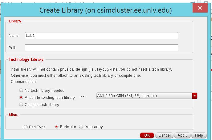
In the library manager, go to File > New > Library and create a library for lab 1 with the following settings:
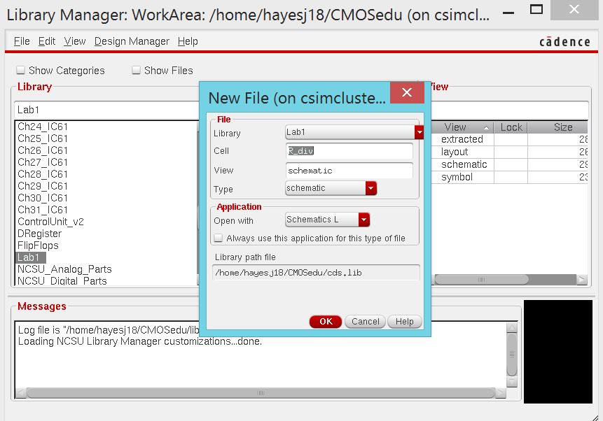
Now
we will create the schematic for our resistive voltage divider.
Go to File > New > Cellview and apply the following
settings:
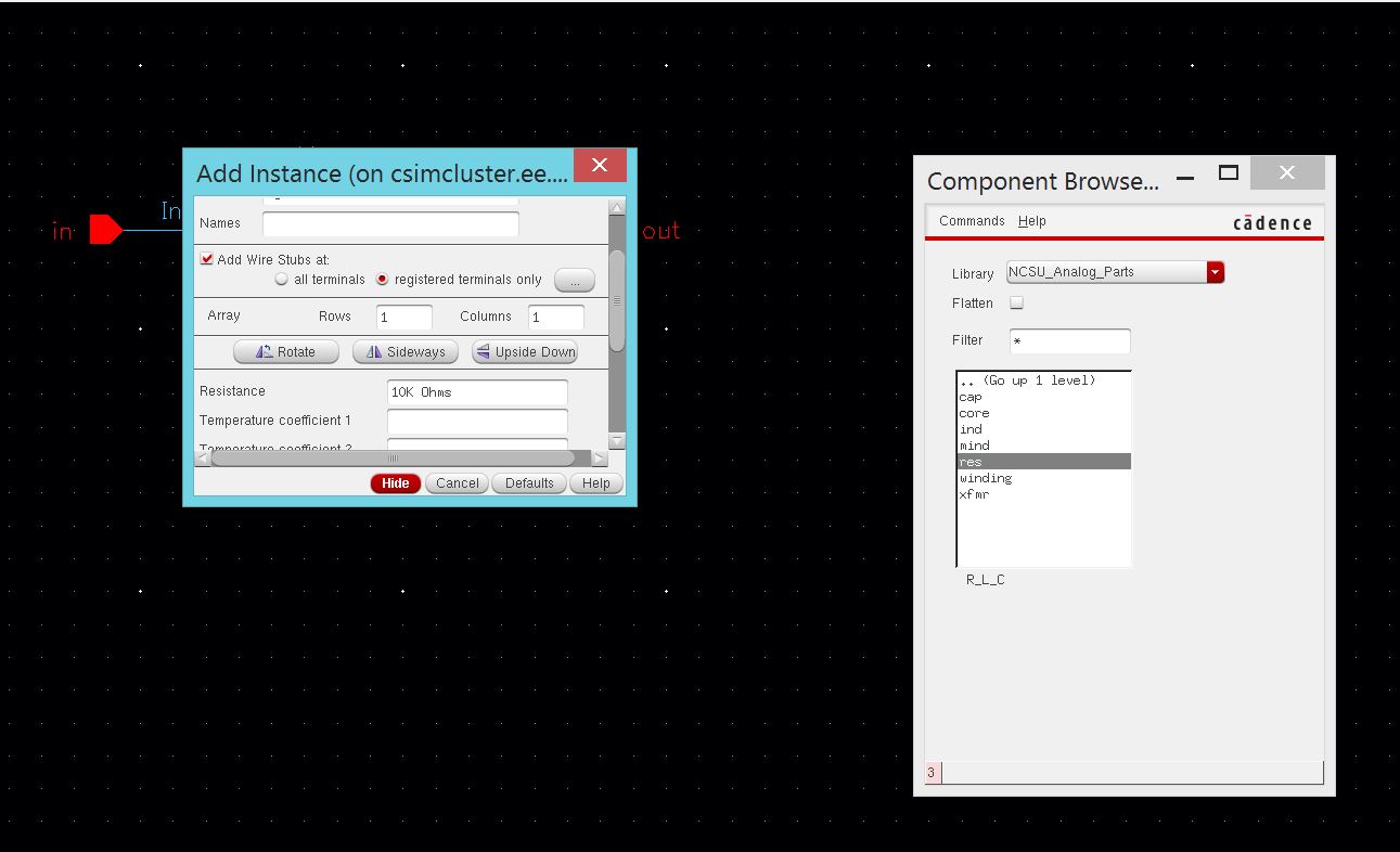
Once
our new schematic is open, we will press "I" in order to a new
component. In this case we will be adding a 10k ohm resistor.
Navigate the component browser to "NCSU_Analog_Parts > R_L_C
> res" to select a resistor. Change the resistor's value from
1k to 10k and place it onto the schematic.
We will also need to add gnd and vdc components, as well as another 10k resistor.
gnd component can be found under NCSU_Analog_Parts\Supply_Nets
vdc component ca be found under NCSU_Analog_Parts\Voltage_Sources.
Set the DC voltage to 1 in component's properties.
Use
the "w" key to draw wires in order to connect the parts together.
Also use the "L" key to write labels for your wires. Add a
label for "in" and "out" at the appropriate locations in the circuits
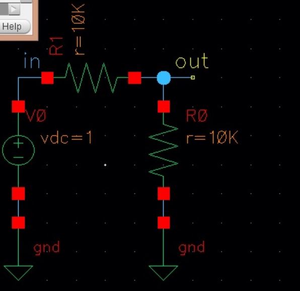
The final schematic should look like this:
Click the "Check and Save" icon at the top-left of the page. Now we can simulate our voltage divider.
Click
"Launch > ADE L" in order to open the Virtuoso Analog Design
Environment. Ensure that Spectre is the chosen simulator by by
selecting it in "Setup > Simulator/Directory/Host" Then click
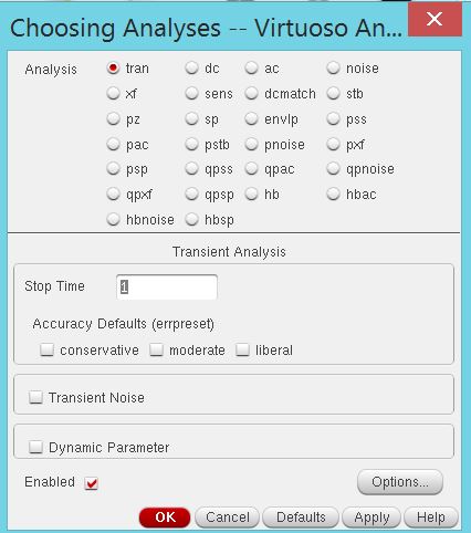
"Choose Analyses" or select "Analyses > Choose" from the dropdown
and setup a transient analysis for 1 second.
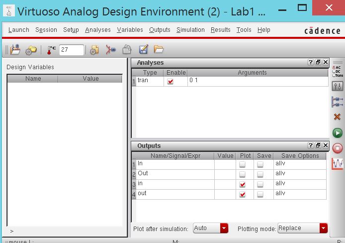
Next,
go to "Outputs > To Be Plotted > Select on schematic." The
schematic window should pop back up, allowing us to click on the wires
we labled "in" and "out" earlier and choose them as our outputs.
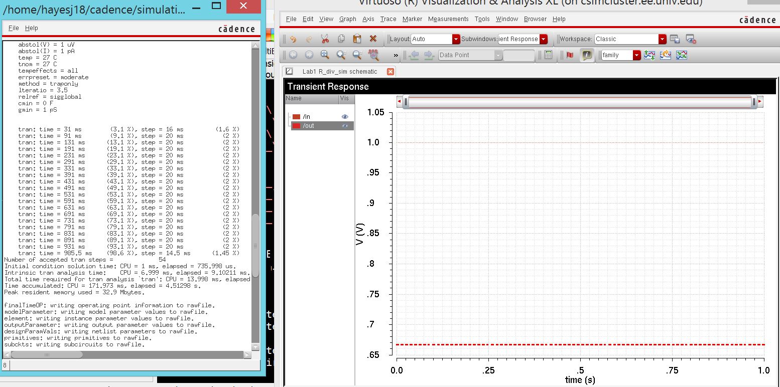
Click on "Netlist and Run."
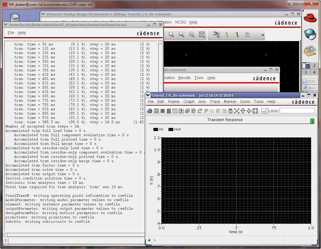
The simulation results should look something like this:
Now we are done with the lab and need to backup our files.
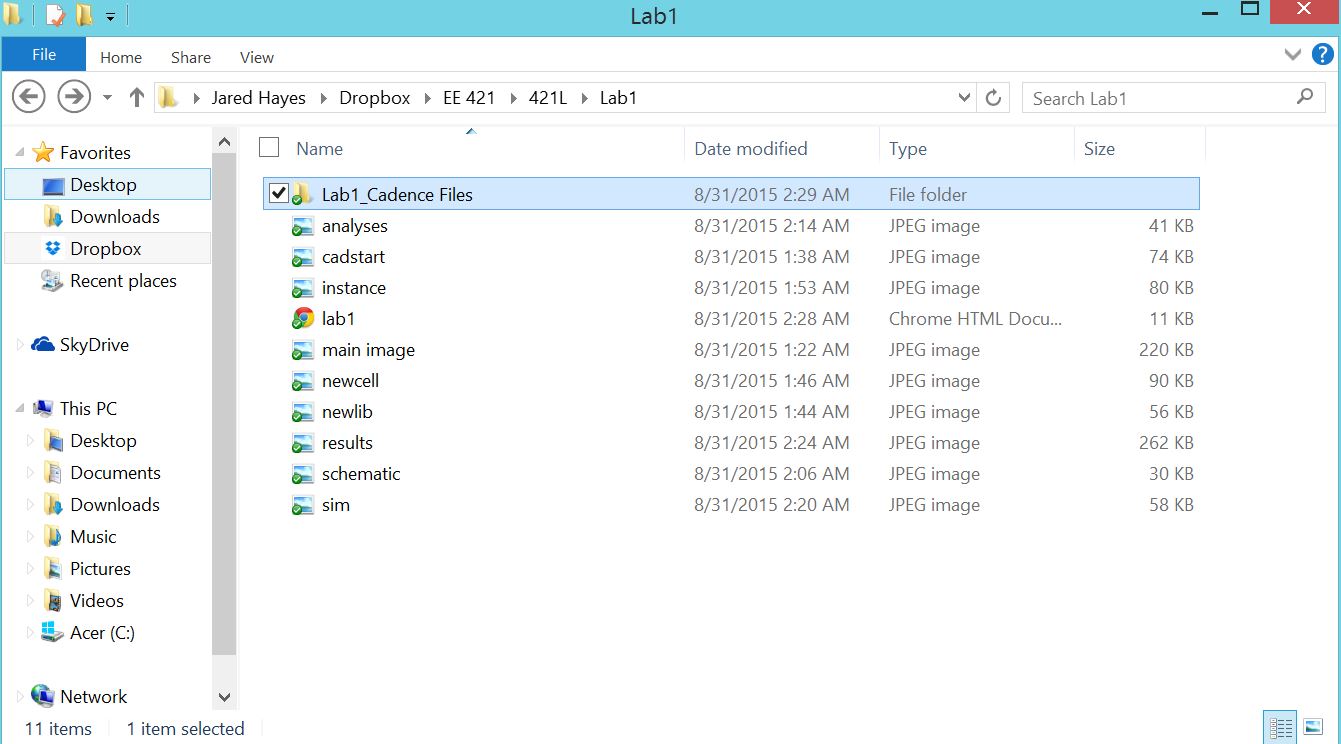
A
copy of my lab report files are saved on a Dropbox folder on my
computer that automatically uploads another copy to my Dropbox account.
I also used Mobaxterm's sftp window to download my Cadence files
for lab1 to my Dropbox folder as well.
return