Lab 1 - ECE 421L

Next, I filled Electric's window space by going to Window -> Adjust Position -> Tile Horizontally.
When these steps were done the Electric window now looked like this:

Next, Electric will be set up for use in ON Semiconductor's C5 process and fabrication through MOSIS.
We will be using the MOSIS scalable SMOS (SCMOS) submicron design rules.
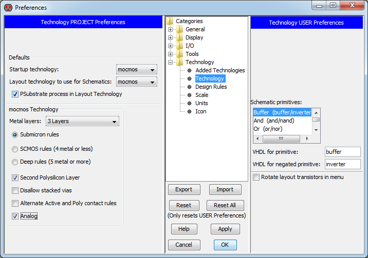
To set Electric up for these settings I went to File -> Preferences and then Technology -> Technology in the window that pops up.
After doing this, I changed all settings to match the image below:
Next I changed the scale according to the submicron design rules.
This was done by going to Technology -> Scale in the above preferences window.

When these settings were changed clicked OK and then chose Mark All Libs in the window that followed.
Then I saved these settings as a library by navigating to File -> Save Library As -> tutorial_1.jelib
Next, the schematic of a resistive divider was created.
This was done by going to Cell -> New Cell, choosing the name R_divider and setting the view to schematic as seen below:

Next I selected the component tab on the left side of the window so Electric looked like this:

Next, the N-Well schematic resistor node was selected by clicking the arrow in the resistor component box and selecting N-Well as seen below:

After placing the component in the drawing area I used the Window menu to zoom-in on the component as seen below:

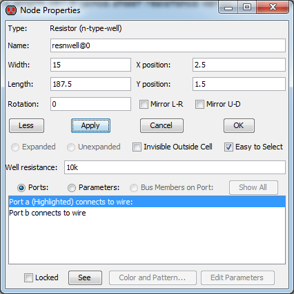
Next, I selected the node by left-clicking on it and then went to Edit -> Properties -> Object Properties. I then clicked the box labeled more and matched the settings shown below:
After pressing OK I needed to refit the component using Window -> Zoom-out.
The finished resistor:

Next, I checked the schematic for errors by going to Tools -> DRC -> Check Hierarchically.
After completing this, I backed up all of my files.
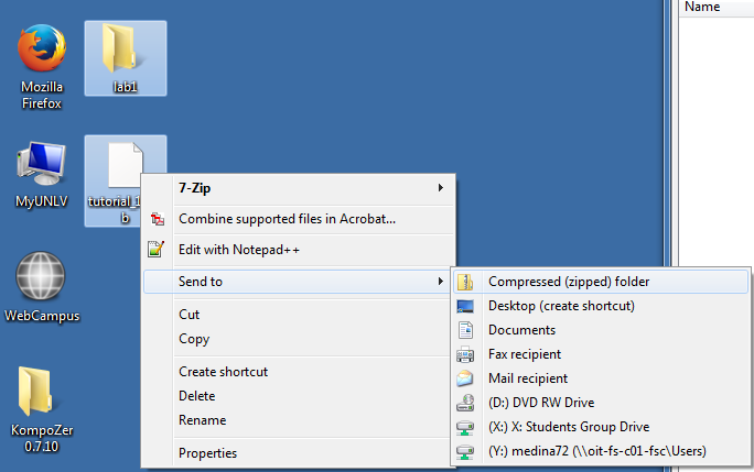
You can zip files and folders using Windows by right clicking files and going to Send to -> Compressed (zipped) folder as seen below:
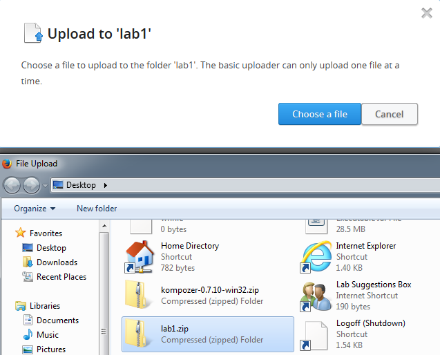
I then used Dropbox to upload this zipped folder as a backup as seen below: