EE 420L Engineering Electronics II Lab - Lab 1
Nha Tran
01/30/2015
NSHE: 2000590233
trann4@unlv.nevada.edu
Lab 01: Review of basic RC circuits:
For
this first lab simulate, and verify the simulation results with
experimental measurements, the circuits seen in Figs. 1.21, 1.22, and
1.24 (use a 1 uF cap in place of the 1 pF cap) of the book.
Your results should be similar to, but more complete than, the
simulation results seen on pages 17 - 23. In your report, and for
each circuit, show the
- Circuit schematic showing values and simulation parameters (snip the image from LTspice).
- Hand calculations to detail the circuit's operation.
- Simulation results using LTspice verifying hand calculations.
- Scope waverforms verifying simulation results and hand calculations.
- Comments on any differences or further potential testing that may be useful (don't just give the results, discuss them).
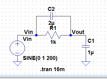
Figure 1.21: LtSpice
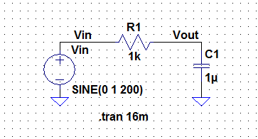
hand calculation: using voltage division to find Vout
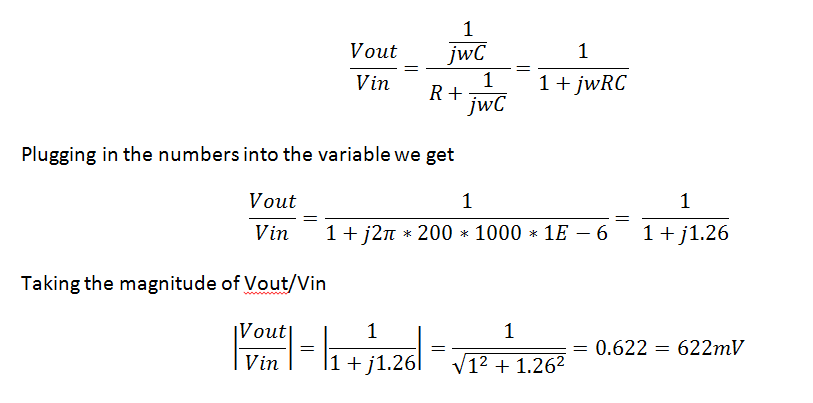
From
the hand calculation we see that Vout is ~ 622mV. The phase angle can
be found by taking the arctan of Vout/Vin, -arctan(1.26/1) = -51.6
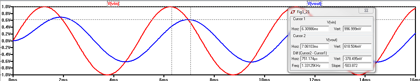
degrees. and from the LTSpice waveform below we also see that Vout is
also ~620mV. The two number matches therefore signifying that our
calculation is correct.
Next we will simulate an AC analysis. to get the phase angle and the magnitude in decibel.
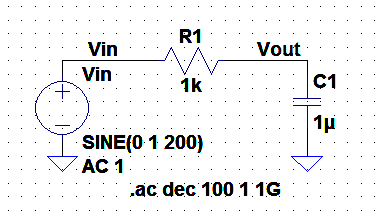
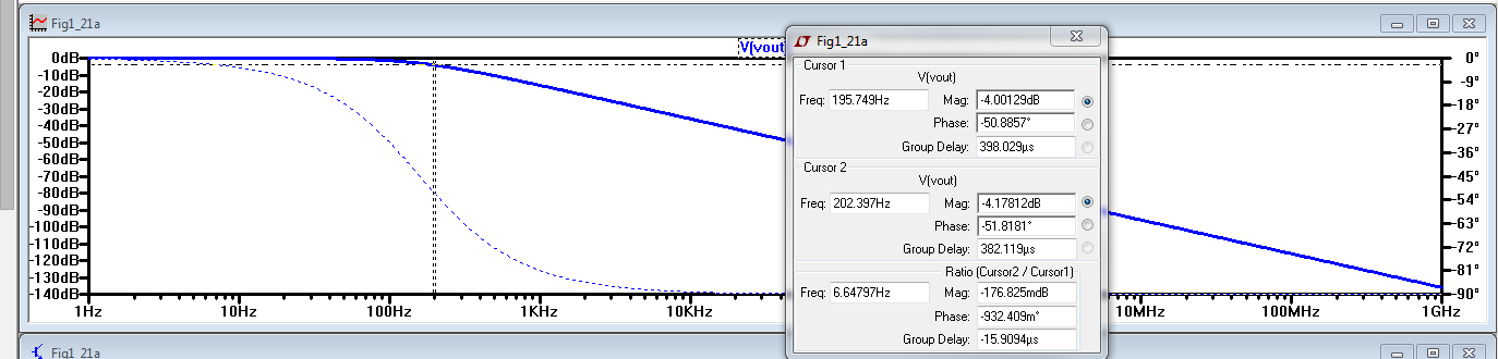
Tables of the magnitude and phase angle of figure 1.21 with varying frequency. As
you can see from the table below as you reach a certain frequency
greater 10 kHz the magnitude and the phase angle remain a constant.
| Frequency | Magnitude (dB) | Phase Angle |
| 1 Hz | -171 udB | 360 mdegree |
| 100 Hz | -1.5 dB | -32.7 degree |
| 200 Hz | -4 dB | -51 degree |
| 1 kHz | -16.1 dB | -81 degree |
| 10 kHz | -36 dB | -89 degree |
| 1 MHz | -76.1 dB | -90 degree |
| 1 GHz | -136 dB | -90 degree |
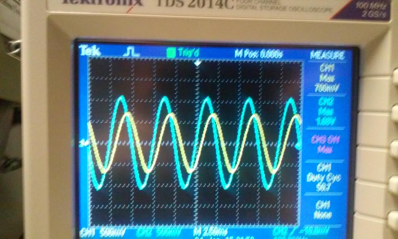
Next
we will simulate the circuit on a breadboard and record its waveforms
using a oscilloscope. As you can see below, Vout is on channel 1 and
Vin is channel 2. Our Input Vin is 1.07 V which is a little bit higher
than the input voltage from LTSpice. We could not get it to be exactly
1V input this is because of the function generator. Our output voltage
is 700mV with a 1.07V Vin, which is proportional to our hand
calculation and LTspice simulation. As Dr. Baker always say "its close enough." next
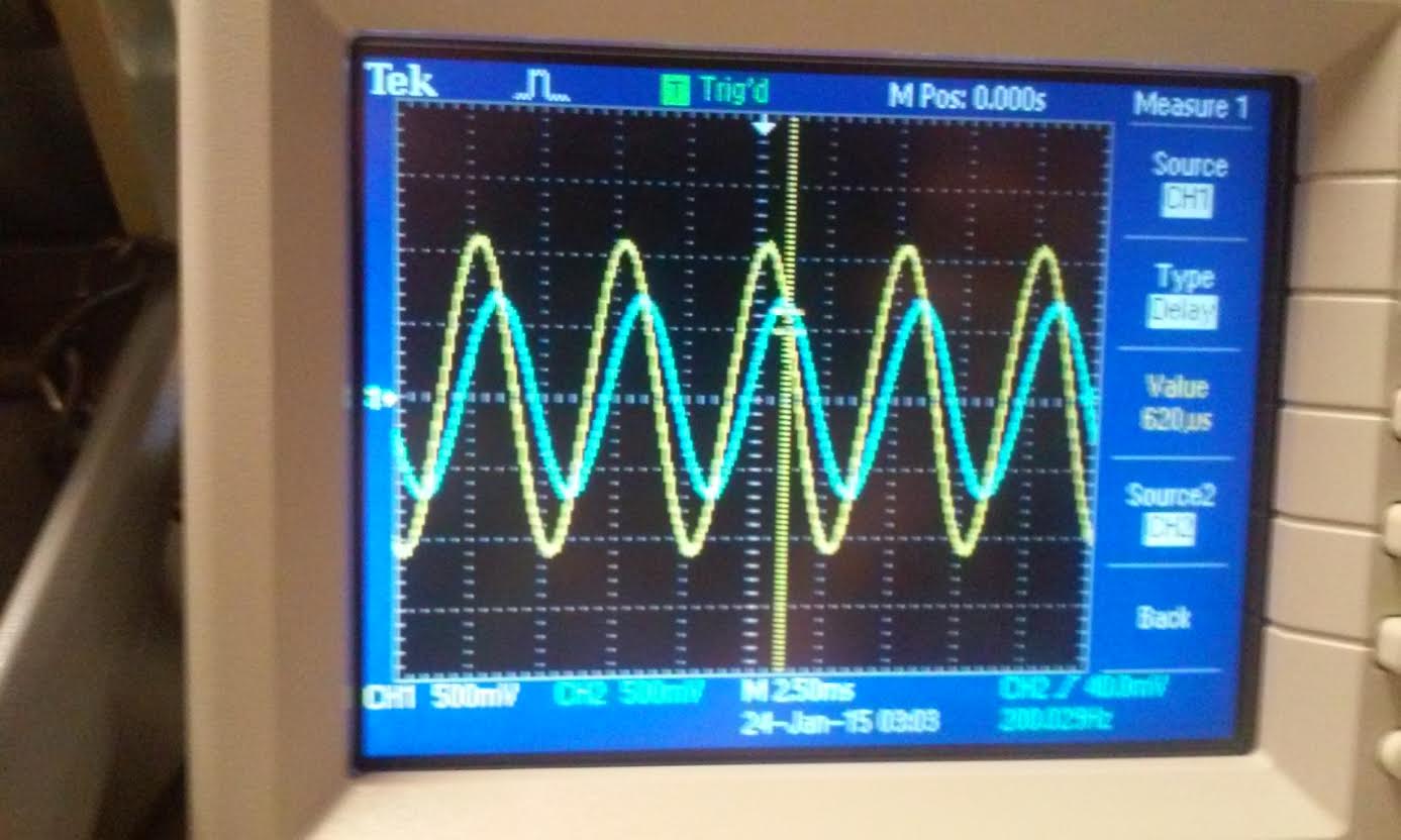
we calculate its time delay by using the equation. td = phase/360f.
time delay = 716.7 micro second. as you can see from the waveform below
we recorded a 620 us time delay.
| Vout | Time delay |
| 
|
As
you can see from the table below the hand calculation and the LtSpice
simulation results is very close, while the oscilloscope reading vary a
little more, this is because the actual component that we used is not
exactly the same value that we use to calculate and simulate. each
circuit component in lab varies from 5% to 10% or even more depending
on who make the parts and its rating. But the result is close enough that we can say that this is good enough for what we are doing in lab.
| Vout | Time Delay |
| hand calculation | 622 mV | 716 us |
| LtSpice simulation | 618 mV | 751 us |
| Oscilloscope reading | 700 mV | 620 us |
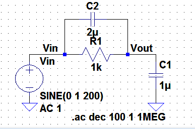
Figure 1.22:
to
find Vout first we have to find the impedance of C2 and R1 first. We
can do this by adding C2 and R1 in parallel using phasors, and we can
call this impedance Z
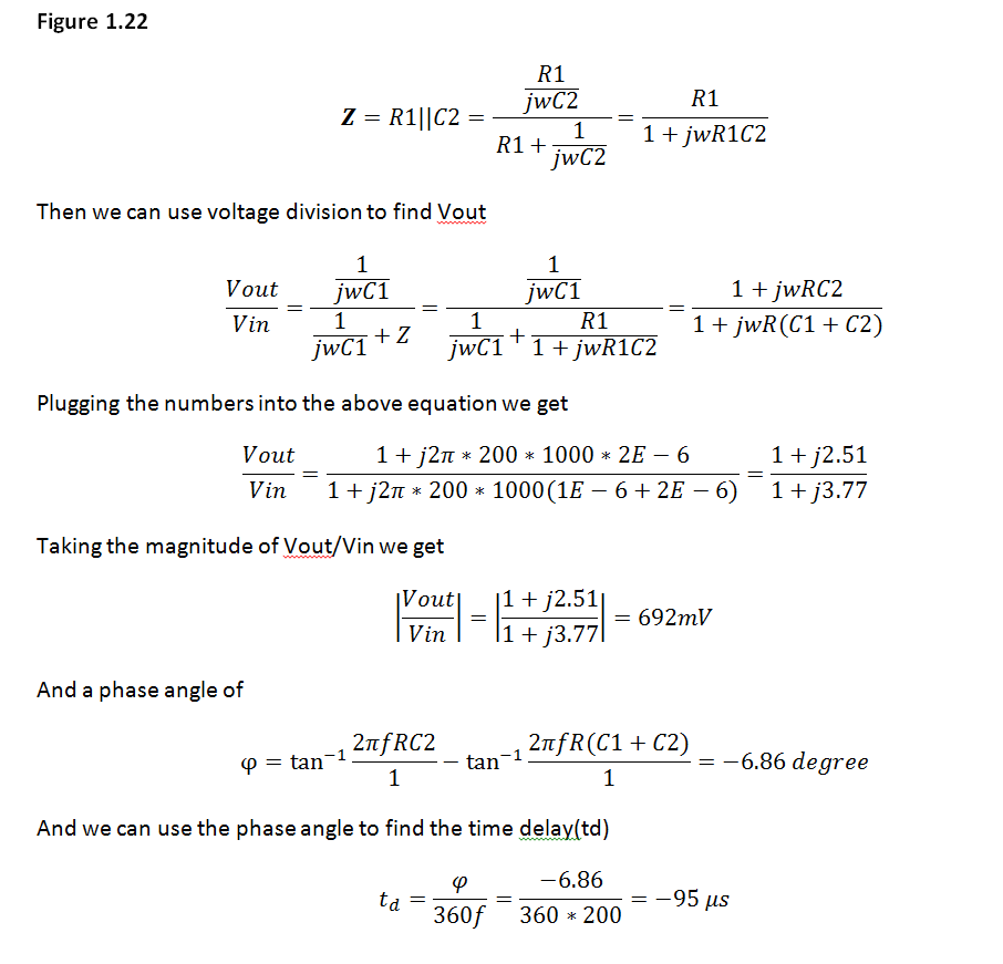
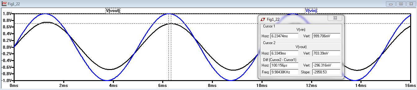
From
the LtSpice simulation below we can see that the output is ~700mV when
the input is 1V. closer inspection of the waveform below you can see
that the output lags behind the input by around 7 degrees.
Again we do an Ac analysis to see the effect when varying the frequency.
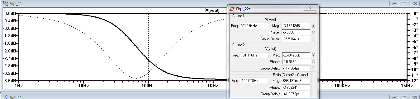
Tables
of the magnitude and phase angle of figure 1.21 with varying frequency.
when the frequency reaches above 1 kHz the phase and magnitude remain
unchanged.
| Frequency | Magnitude (dB) | Phase Angle |
| 10 Hz | -84.5 mdB | -3.53 degree |
| 100 Hz | -2.48 dB | -10.5 degree |
| 200 Hz | -3.18 dB | -6.81 degree |
| 1 kHz | -3.51 dB | -1.47 degree |
| 10 kHz | -3.52 dB | -148.6 mdegree |
| 1 MHz | -3.52 dB | -1.52 mdegree |
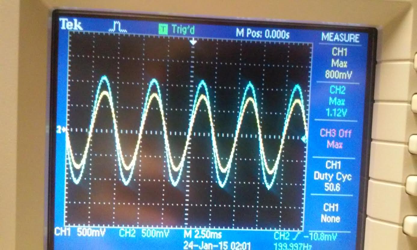
Next
we measure our circuit with an oscilloscope as you can see from below
our Vout is measured at 800mV with a 1.12V input. this value is close
enough to our hand calculation and LtSpice simulations. the difference
in voltage is negligible. Our calculation for time delay was ~100us while our oscilloscope gave us a value of 150us.
| Vout | time delay |
 | 
|
Again
similar to the discussion with figure 1.21. the result from the hand
calculation and spice simulation matches very closely while the actual
reading of the component does not match perfectly but is still within
the range of the expected value.
| Vout | time delay |
| Hand Calculation | 692 mV | 95 us |
| LtSpice simulation | 703 mV | 100 us |
| Oscilloscope | 800 mV | 150 us |
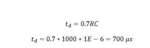
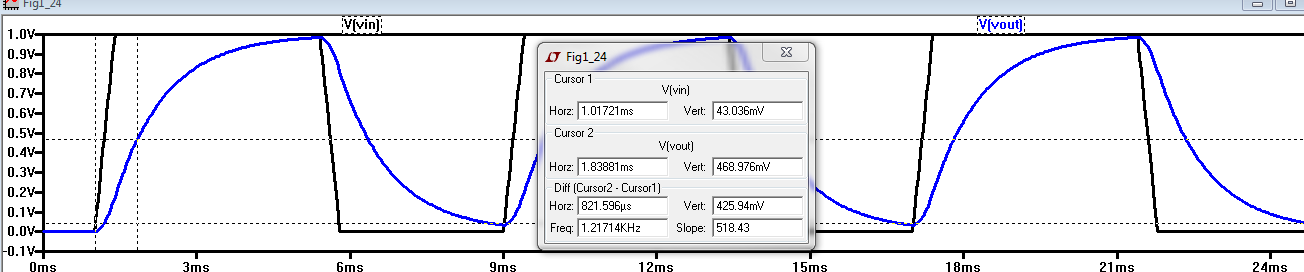
Figure 1.24
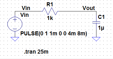
to find the time delay for an RC circuit with a square wave input we use the equation.
and
the simulation from Ltspice yield 820 us for the time delay. this
varies with the hand calculation because of the cursor that i placed,
the number is very small so its very diffficult to set the cursor to
make it accurate like the hand calculation, but it is within the
ballpark of the hand calc so its good value to use for estimation.
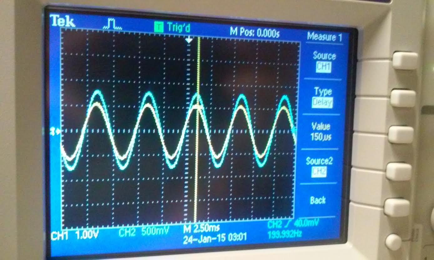
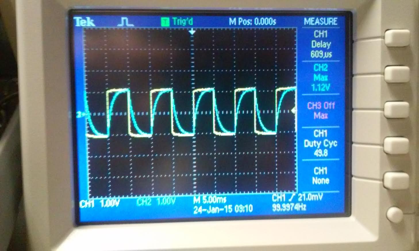
Again
the value from the oscilloscope is different from our hand calc and
simulation was discussed in figure 1.21 and 1.22. and again the input
value was 0V to 1.12V not 0 to 1V. so it is expected that the delay is
little off but again still fall within the ballpark of our expected
value.
Time delay for figure 1.24.
| time delay |
| hand calculation | 700 us |
| LtSpice simulation | 821 us |
| Oscilloscope | 609 us |
Conclusion: in
conclusion doing hand calculation and simulation with the values that
is given can vary greatly with the actual values that the component
gives. because each component values is so small like micro ohm,
farads, etc. and the time delay is also very small so its very hard to
exactly match the oscilloscope reading with the hand calc. but if the
hand calc and the reading is within range of each other than it is good
because we just want to estimate the delay when we make our circuit.
Lastly zipping up the work and emailing it to myself for backup. This folder (NT_ee420L_lab1)contain all the hand calc, simulation, and pictures associated with this lab.
Return to EE420L front page