the mirroring on the devices that accept the input-pair drains. Most literature implement the mirror opposite
from where the input-pair drains enter the cascode structure. Are there any advantages to doing it one way
versus the other.
This is a very good question. You are saying it's most common in the literature to connect the gates of M11/M12
to the drain of M9 instead of Vbias4 and connect the gates of M5 and M6 to Vbias1 instead of the drain of M7
as seen below with redlines?
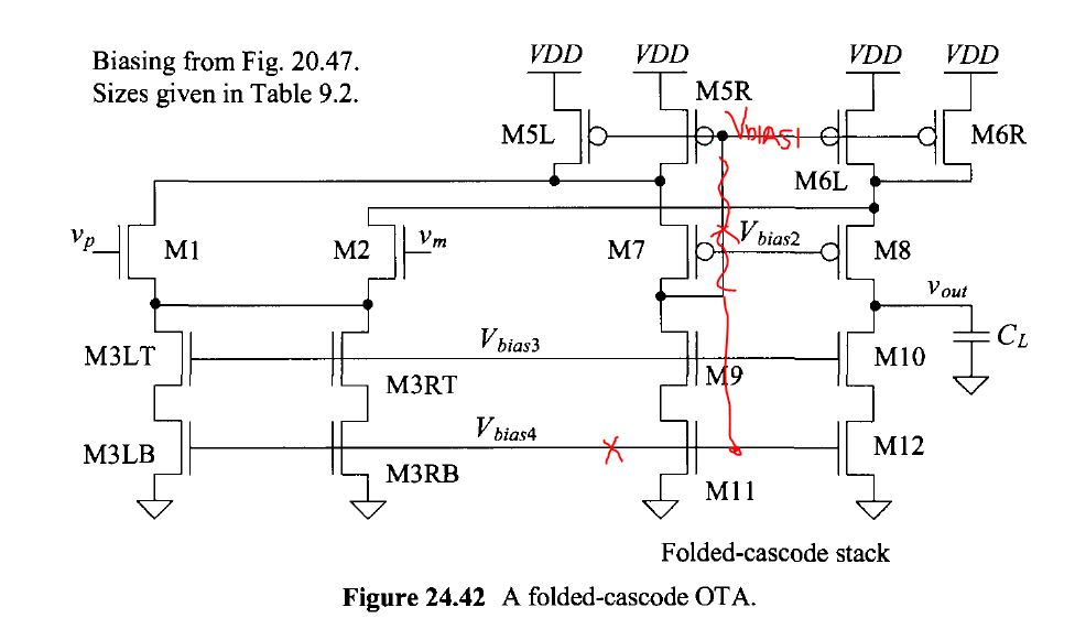
The unmodified topology seen in Fig. 24.42 will be a little bit slower since M9/M11 will have to discharge
the gate capacitance associated with PMOS devices M5L, M5R, M6L, and M6R. In the modified version
M7/M5 will only charge the gate capacitance associated with M11 and M12, 2 devices versus 4 and smaller
widths for the NMOS than the PMOS. Practically, the speed difference is likely neglibible for most designs.
So why is this topology used in the book? The answer is that it is better for reliable biasing. To understand
this imagine, using the modified (redline) topology, that M5L, M5R, M6L, and M6R each source only 4 uA
(16 uA total) while M3L and M3R (the tail current sink for the diff-pair) each sink 10 uA (20 uA total). Of
course this doesn't work (this is bad design, dueling current sources). The tail current sink will start to triode,
as will the diff-pair, until its current drops to 16 uA to equal the current sourced by M5 and M6. Of course
then M7-M12 will be off!
The reader may feel that this, 4 uA in each PMOS instead of 10 uA, is unrealistically poor matching (it's not).
Further, as seen in Fig. 9.31, it's very easy to change the drain-source voltage of a MOSFET, at a fixed gate-
source voltage (bias voltage), and see a variation of 6 uA drain current in a device.
Note that here we are assuming that the current mirrors were designed based upon the information given in
Ch. 20 of the book. For example, M7 and M8 (or any of the other wide-swing cascode current mirrors in the
OTA) are biased to ensure that M5 and M6 are not on the verge of triode, see bottoms of pages 641-642.