UNLV Computer Engineering
Undergraduate
Email: batuj1@unlv.nevada.edu
LinkedIn: https://www.linkedin.com/in/jerrod-batu-17321b248
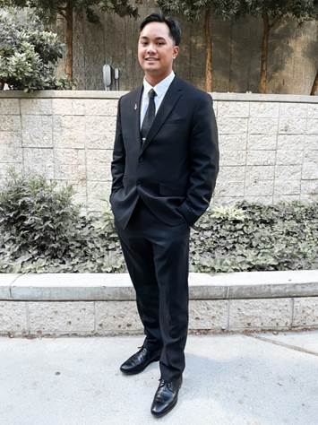
About Me
I am a fifth-year student
at the University of Nevada, Las Vegas pursuing a Bachelor of Science degree in
Computer Engineering and a Minor in Mathematics. I am currently the
recording secretary and events chair for Tau Beta Pi. Some of my hobbies
include researching and learning about computer builds, sneaker collecting,
working out, listening to music from multiple genres, and searching around
Vegas for amazing places to eat.
- PC Building
- Sneaker Collecting
- Music
- CPE 200L
- CPE 300L
- EE221L
- CPE 200: “DE2 Says”
- CPE 302: “Digital Clock
VHDL”
- Quartus II
- Dip Trace Practice
- Raspberry Pi Pico
- Soldering Practice
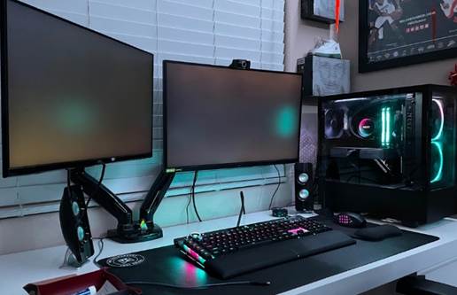
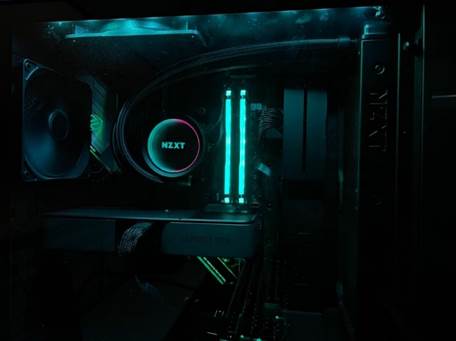
PC Specs:
AMD Ryzen
5 5600X
Corsair
Vengeance RGB Pro 32 GB DDR4-3200
Samsung 970
Evo Plus 2 TB M.2-2280 SSD
NVIDIA
3060 TI FE
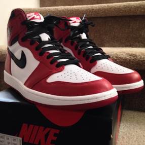
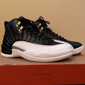
First sneaker I ever
bought Most recent sneaker I own
(2015 Jordan 1 Chicago)
(2022
Jordan 12 Playoff)
Albums I’m Currently
Listening To:


No Saints Loading Master of Puppets Astroworld
By
Manila Grey By Metallica By Travis Scott
CPE
200L:
Lab
2: TinkerCad Intro
Lab
3: Altera Quartus Intro
Lab
4: Adders and Multiplexers
Lab 5:
System Verilog Intro
Lab
6: Sequential circuits and Synopsys VCS
Lab
7: 7 Segment Displays and LUTs
Lab
8: Finite State Machines in System Verilog
Lab
9: DE-Series Basic Computer and NIOS II Processor
Final:
Simon Says on DE2 Board
CPE
300L:
Lab
1: System Verilog Gates
Lab
2: Continuous Assignments, Primitives, Delays, and More
Lab
3: Testbenches and Combinational Circuit Designs
Lab
4: Latches and Flip-flops
Lab
5: Finite State Machines in Verilog
Lab
6: General Datapath
Lab
7: Control Unit for Summation Algorithm
Lab
8: General Datapath and Timing
Lab
9: Single Cycle MIPS Datapath
Lab
10: Pseudo-instruction Implementation on MIPS Datapath
Final: 8-bit Microprocessor (SMP8)
EE
221L:
Lab
1: DC Circuits & LTspice
Lab
2: Multisim
Lab
3: Ideal AC Circuits, Capacitors & Inductors
Lab
4: Practical AC Circuits, Capacitors & Inductors
Lab
5: Soldering Lab
Lab
6: Op Amp
Lab
7: Linear Regulators
Lab
8: Electric Power Transformers
Lab
9: Frequency Response & Filter Designs
Final: Mini Piano Using LM555 Timer
CPE 200L: “DE2 Says”
My partner, Matthew
Labrador, and I implemented a Simon Says game onto the DE2 Cyclone IV
board. We accomplished this by using finite
state machines. The user would have 4
input options where the correct code would be indicated on the LEDs on the
board.
This is the RTL view
showing our combinational logic block, win condition outputs, and 3 decoders
for our 7 Segment display output.
This is the DE2 Cyclone IV
board displaying the outputs of a win condition.
Video
showing no win condition
CPE 302: “Digital Clock VHDL”
My partner, Robert
Lonasco, and I designed a digital clock through VHDL in our Digital System
Design class. The functions of the clock
would work alongside the clock divider module as well as include user inputs as
a hand-held digital clock would use.
This digital clock would be revealed on the 7-segment display through
military time format.
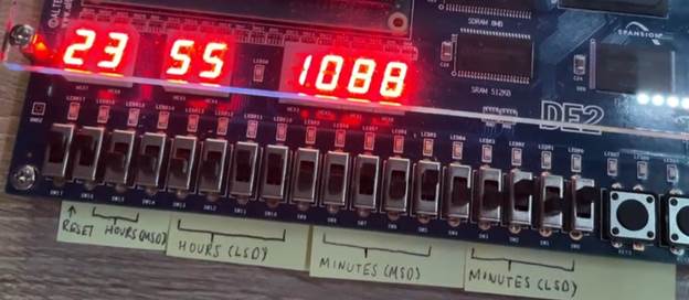
This is an example of our digital
clock showing 11:55:10. The first two 7-segment displays are left as “8” by
default.
Robert and I attempted to
have our design output onto a VGA display; however, there were a few
complications. We had issues configuring
the functionality on how the seconds, minutes, and hours would increment as
they would need a PLL module. We did not
learn how to use this PLL module, and we, unfortunately, were not able to
output the functionality of our clock onto the VGA monitor.
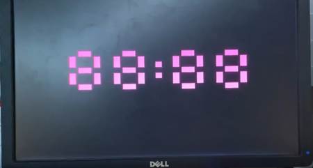
This is the VGA monitor
displaying 88:88 as default values.
Video
showing Digital Clock through VHDL
Quartus II on VirtualBox
Throughout the middle of
May to the end of June, I was researching about Opal Kelly and its use with
Quartus II 13.1. There were a few
licensing issues I came across regarding Quartus II 13.1 requiring a license
for Verilog usage throughout its platform; therefore, I assumed that the
problem was utilizing Quartus on my Windows PC.
I theorized that Quartus may possibly work along with Opal Kelly if I
were to create a virtual machine on my MacBook Air, so I created a virtual
machine that would run Quartus II. It
came to my attention that the licensing problem occurred from utilizing the
13.1 version of Quartus II, and Quartus II 13.0 sp1 did not have this
issue. Opal Kelly would only work with
Quartus II 13.1, and I had to conclude my research regarding Opal Kelly
here. Nonetheless, I created a guide on
any student that may need Quartus II 13.0 sp1 if the student were to need this
information in the future.
Link: “How
to Create a Virtual Machine on macOS Running Quartus II”
Dip Trace Practice
While I was having issues
with Opal Kelly and Quartus II, I learned how to create PCB schematics through
Dip Trace. Dip Trace is a PCB Design
software equipped with an auto router, schematic capture through multi-level
hierarchy, 3D previews, Gerber outputs, etc.
Unfortunately, I did not have time to submit these PCBs to be printed, but
I did gain a lot of experience and practice on how these PCBs are created and
how each SMD component can be routed throughout the board.
This is an image of the
Infrared Sensor PCB. Some of the routing
is done through the bottom of the PCB, but you will be able to view this by the
provided link. The Infrared Sensor PCB
will detect any infrared movement through the sensor placed onto the PCB. An LED will light up if movement is detected.
This is an image of the
Raindrop Sensor PCB. Some of the routing
is done through the bottom of the PCB, but you will be able to view this by the
provided link. The Raindrop Sensor PCB
will detect raindrops through the on-board pressure plate. An LED will light up once raindrops are
detected.
This is an image of the
Ultrasonic Sensor PCB. Some of the
routing is done through the bottom of the PCB, but you will be able to view
this by the provided link. The
Ultrasonic Sensor PCB will detect any sound through the on-board antenna. LEDs will light up once sound is detected.
This is an image of the
Wi-Fi Main Controller PCB. Some of the routing
is done through the bottom of the PCB, but you will be able to view this by the
provided link. The Wi-Fi Main Controller
PCB will control all the sensor-detecting components and compile all of them
together through a Wi-Fi connection.
Raspberry Pi Pico
Throughout the last few
months of my research, I was practicing software and hardware implementation
through a Raspberry Pi Pico programmed through Thonny
Python IDE.
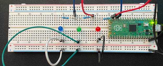
This is an image of the
Raspberry Pi Pico that would synchronously through a set time interval.
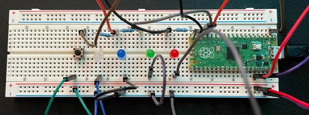
This is an image of the
Raspberry Pi Pico that would synchronously light up all LEDs within the same
time interval when a pushbutton is pressed.
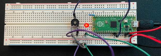
This is an image of the
Raspberry Pi Pico that would increase or decrease brightness depending on the
resistance provided through the potentiometer.
Soldering
Practice
Whenever I had downtime
throughout my summer, I would go to the lab and practice my soldering. My first instance of soldering was in the
EE221 Lab, and I was struggling with solder control. Throughout my research in the lab, I became
more comfortable with soldering through practice soldering boards, kits, and
SMD components.
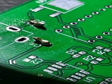
This is an image of my
first few soldered SMD components on a PCB.

This is an image of my
soldering of banana jacks on a PCB.
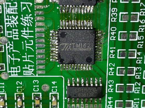
This is an image of my
soldering through chip components on the practice soldering kit.