Opal Kelly
Introduction (Tutorial)
By: Chris Barr
Email: chrisbarr74@gmail.com
Last Modified: 01/23/2021
Welcome to the How to
Opal Kelly ZEM5305-A2 Edition.
In this quick start-up tutorial, the user will understand how to setup their
ZEM5305 board to access and configure the GUI, as well as the programmable
file.
This is the ZIP of all
the files created throughout this tutorial, click the image below to download.
Note: This ZIP does not include files from Opal Kelly.

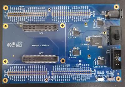
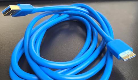
Materials used in this
tutorial:
|
BRK5305 |
ZEM5305 |
USB
3.0 A to USB 3.0 Micro-B Receptacle |
|
|
|
|
Software Used:
-
Opal
Kelly Front Panel SDK
-
Quartus II 13.1 (64/32 bit)
-
Text
Editor (Notepad++)
Note: The Opal Kelly Front Panel
SDK software can only be downloaded by an approved registered customer with
Opal Kelly (aka bought their product(s)).
To register the product, go to this link here. Google emails do not work L
Make sure all
materials and software are acquired before passing this point.
Page Directory:
|
Jump
to Link |
Description |
|
Creating an .XML file to
program and design the graphic user interface. |
|
|
Creating an
.RBF file to program the Altera Cyclone V chip. |
|
|
Showcases the output capability
of using an Opal Kelly with the tutorial code. |
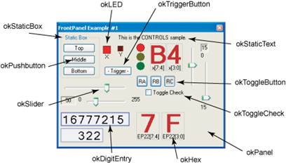
The Front Panel is
capable of inputting buttons, sliders, digits, and hex. Here’s an image from
the Opal Kelly documents showcasing that, and more.
Opal Kelly has a
document with examples of all the XML components located here
This tutorial will
cover using pushbuttons and digit inputs. Opal Kelly’s Front Panel SDK and
Notepad++’s Text Editor will be used in this portion of the tutorial.
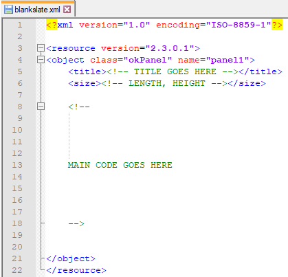
To begin, an XML file
can be created by using a text editor. In this tutorial Notepad++ is going to be used.
For a blank slate, here’s the minimum requirements. This file can be found in
the ZIP above.
However, a premade
file will be used, and can also be found in the ZIP above. The filename will be
called “frontpanel.xml”
Open this file, the contents should be the same as the code shown below. This
code has one digit input, and two pushbutton inputs.
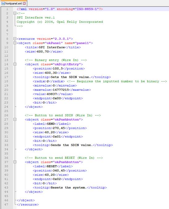
For the digit entry,
it allows users to enter digits by mouse/keyboard.
The user can either hover the mouse over the number and use the scroll wheel,
or type the number in manually.
The properties of this input can manipulate the decimal point value, radix, and
min/max size.
![]()
For the pushbutton
entry, its modeled like a physical button.
When the pushbutton is pressed, a logical ‘1’ will be sent in as an input.
Whereas if it’s not pressed, it will send as a logic ‘0’.
![]()
Download the FrontPanel SDK software from the Opal Kelly website here
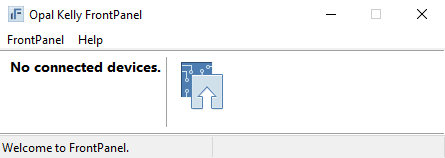
When downloaded,
launch the software and this window should pop-up.
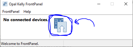
Go ahead and
drag-and-drop the file “frontpanel.xml” into the icon shown below
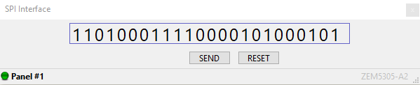
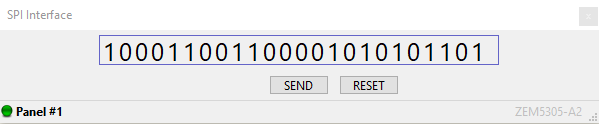
A new window will
pop-up with the digit entry and pushbuttons. These will be the inputs sent into
the programmable file.
There’s a 24-bit digit input, with a send and reset buttons
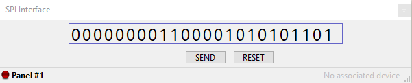
In this tutorial, the
program will take in the 24-bit input and only be sent when the button “SEND”
is pressed. Only at the very beginning, and any time the program glitches,
there’s a “RESET”
button to restart the program.
For the programmable
file, Altera’s Quartus II 13.1 will be used and the
code will be in Verilog. Download Quartus 13.1 here
Because the Opal Kelly ZEM5305 supports the Altera Cyclone V FPGA series, be
sure to include the Cyclone V device support files when installing Quartus.
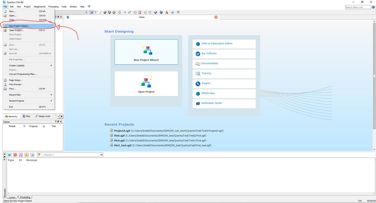
Launching the Quartus 13.1 application, go to File
> New Project Wizard…
And then hit “Next
>”
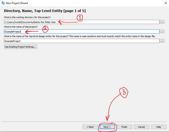
And then (1) select the
folder you want the project to be accessible in, (2) select the name of the
project, (3) hit “Next >”
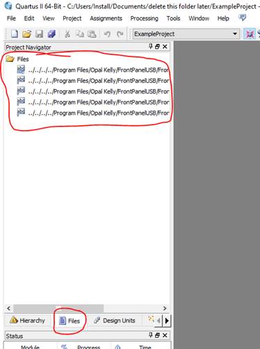
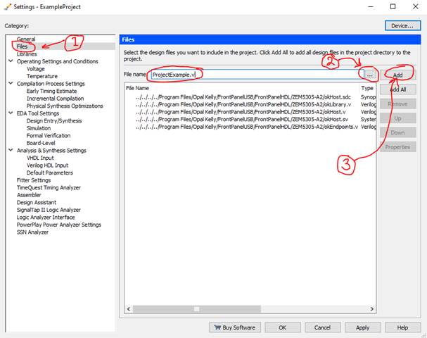
The next page will ask
to select any files needed for the project. Navigate to the ![]() and select these files shown below.
and select these files shown below.
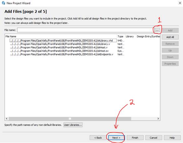
These files can be
found inside a folder called “Opal Kelly”. It should come preinstalled with the
download of the Front Panel SDK. By default, it should be located in Program
Files.
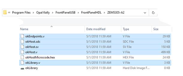
Once located, go to this folder:
Opal Kelly > FrontPanelUSB > FrontPanelHDL > ZEM5305-A2
This folder will have all the HDL files in regards to the ZEM5305 FPGA.
Add these highlighted files into the Quartus project
***Make sure you add “okHostMicrocode.hex”
to the project directory folder***
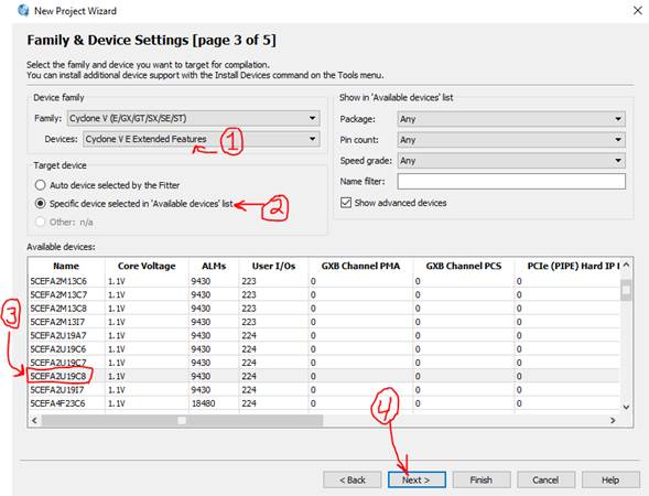
Next, Quartus will ask for what Family and Device will be used.
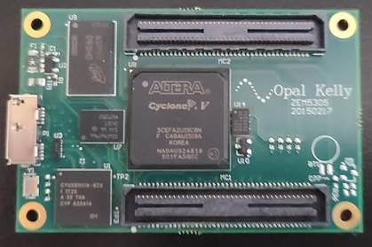
The FPGA chip used on the ZEM5305 is called the Cyclone V E (5CEFA2U19C8N).
To minimize the list, under the (1) Devices drop down menu, select “Cyclone V E
Extended Features”. And then (2) circle “Specific device selected in ‘Available
devices’ list”.
Scroll down and (3) select the device “5CEFA2U19C8”. Then (4) hit “Next >”
Fun Fact: The FPGA device name “5CEFA2U19C8” can be seen on top of the Altera
Cyclone V FPGA chip.
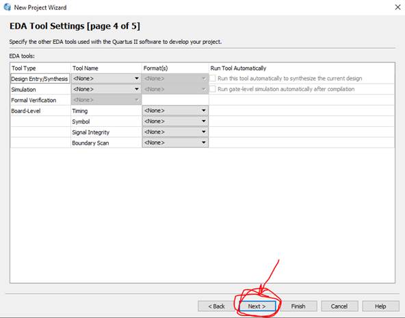
No changes need to be
made here -- hit “Next >”
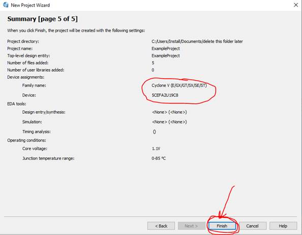
Make sure this last page
matches up with the image shown below. Then hit “Finish”
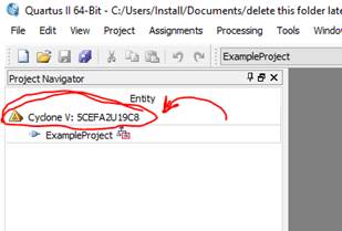
If an error occurs,
try reloading Quartus and make sure the device
“5CEFA2U19C8” is correctly shown under the project navigator
If this does not match, go to the toolbar at the top and left click
Assignments > Device…
Then left click the correct device again
And make sure the
files that were selected earlier are loaded into the project, as shown below
If not, go to
Assignments > Settings… > Files
And then left click the ![]() again to load all the files into the project
again to load all the files into the project
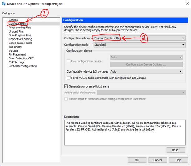
At the toolbar from
the top, go to
Assignments > Device… > Device and Pin Options… > Configuration
Set the “Configuration Scheme” to Passive Parallel x16
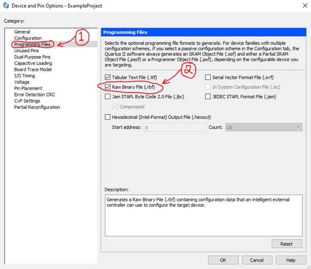
Under Category, click
on Programming Files. Inside, make sure the Raw Binary File (.RBF) is
selected
This is important because this will be the output file placed in the Front
Panel software to program the board
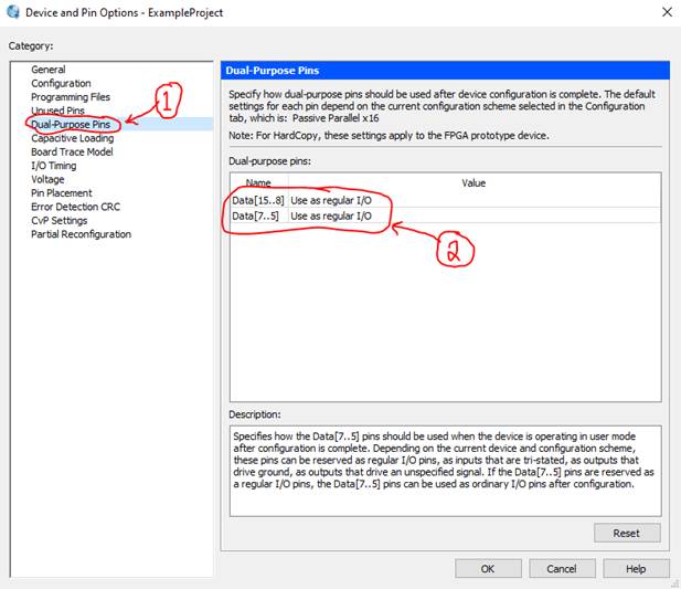
Under Category, click
on Dual-Purpose Pins. Inside, set everything to “Use as regular I/O”. If you
have DCLK, set it as “Use as programming pin”
Press “OK” at the
bottom of that window. Go to
Assignments > Settings… > EDA Tool Settings
Make sure all tool names are set to “<None>” as shown below
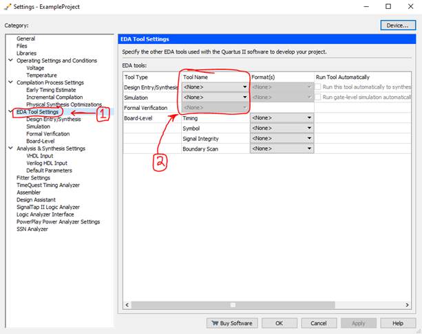
Press “OK” at the
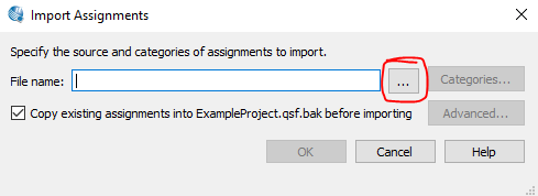
bottom. Now go to
Assignments > Import Assignments…
Use the browse button ![]() to locate the “zem5305.qsf” file in the Opal
Kelly folder
to locate the “zem5305.qsf” file in the Opal
Kelly folder
This can be grabbed from
Opal Kelly > FrontPanelUSB > Samples >
Counters > ZEM5305-VHDL
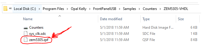
Select the .QSF file
and click the “Advanced…” button on the Import Assignments window
Under Import Options section, make sure the “Imported entity assignments
replace current entity assignments” is checked
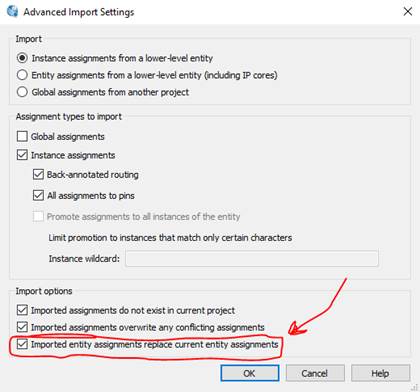
Now press “OK” in the
Advanced Import Settings window, and press “OK” again in the Import Assignments
window.
A message will appear from the console saying
![]()
For this tutorial, a
premade file (found in ZIP above) will be used. This file is called “ProjectExample.v”. Add this inside the project directory
folder
To add this file in Quartus, from the top of the main
window
Assignments > Settings… > files
Select the browse ![]() button and Add the Verilog file ProjectExample.v
button and Add the Verilog file ProjectExample.v
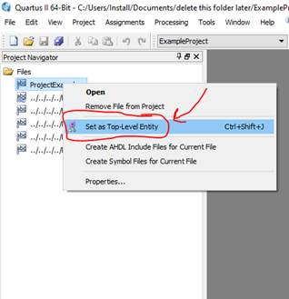
Hit “OK”. Under the
Project Navigator go to the Files tab and right-click the ProjectExample.v
file and select Set as Top-Level Entity
At this point in the
tutorial, the ProjectExample.v can be used as a
template to create another program
Now hit the Start
Compilation button within the Quartus toolbar as
shown below
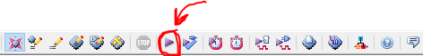
Depending on the
computer you’re using, this may take a few minutes
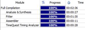
When the project is
finished compiling, go to
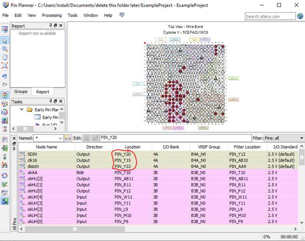
Assignments > Pin Planner
Under pin location SDIN, clk16, and dlatch should be
blank. Go ahead and fill it with the corresponding values shown below
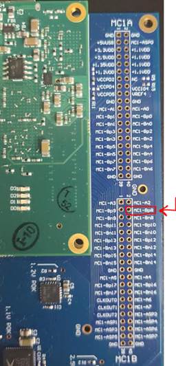
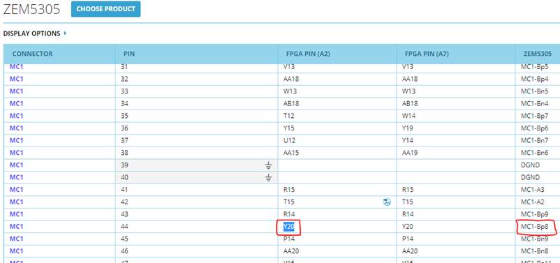
These pins can be
found on the Opal Kelly website, click the link here to view the pin
list
Choose the pins based on where the preferred location of the port would be
Just make sure that if outputting a clock, choose a pin location with the ![]() symbol next to it – just like PIN_T15
symbol next to it – just like PIN_T15
If the pin locations
have been decided, re-compile the code using the same ![]() as before.
as before.
Within the projects file directory, search for the output file ExampleProject.rbf
This file could be inside a folder within the project directory called “output_files”, or within the project directory itself
Make sure the Front Panel SDK software is launched, and drag-and-drop the file
in the location shown below
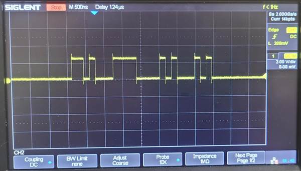
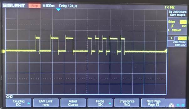
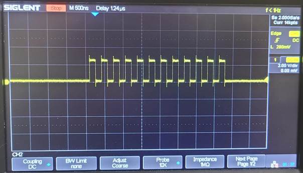
Once the files are
both dragged-and-dropped into the Front Panel SDK software, the output of the
ports can be tested on an oscilloscope.
Here’s a few tests to showcase the example working properly with the GUI
created using XML file and the program created from the RBF file.
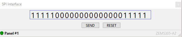
Test 1:
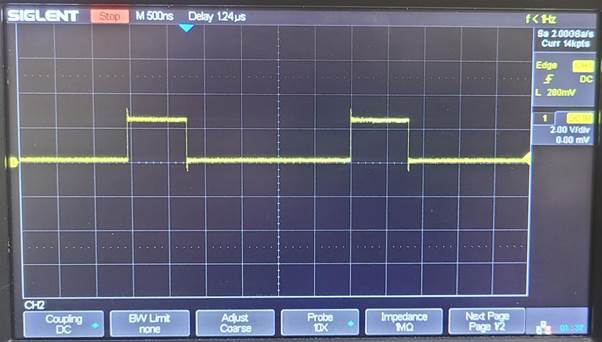
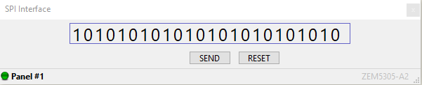
Test 2:
Test 3:
Test 4: