Lab 4 - ECE 421L
This prelab begins with the following questions and asks us to complete tutorial 3.
1. What does the Bindkey q do?
Bindkey "q" opens the properties window allowing the user to edit the value of an instance.
2. Which two Cell Views are used when doing an LVS?
Schematic and Layout
3. What is the difference between the nmos and nmos4 schematic cells?
The nmos does not have a body connection while nmos4 does.
4. How do you select the MOSFET models in the ADE window? What does ADE stand for?
Launch -> ADE L -> Setup -> Model Library Setup. Under Global Models, we click on the side to "add model file", then "Choose Model File", and go to the root directory. There we select the "ncsu-cdk-1.6.0.beta" folder -> models folder -> spectre folder -> standalone folder. For the PMOS/NMOS MOSFET we choose the file ami06P.m/ami06N.m.
5. What is the difference between moving and stretching?
Moving will change the position of the whole object while stretching changes the dimensions of the selected area.
6. How do you layout a rectangle on the metal1 layer?
To layout a rectangle on the metal1 layer, we select the metal1 from the layer window on the left side. Then we use bindkey "r" to start drawing the rectangle. Click to select a starting corner, drag to the desired size, and click again to complete.
7. What does the ! indicate at the end of gnd! and vdd!
Global variable
8. What do the acronyms LSW and CIW stand for?
Left Side Window and Command Interpreter Window
9. How is the ruler used? Cleared?
Bindkey "k" is used to bring out the ruler and bindkey "shift-k" will clear the ruler.
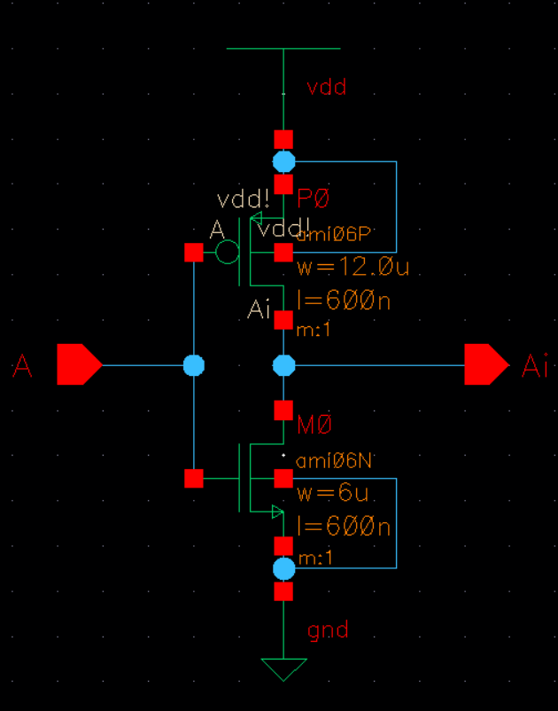
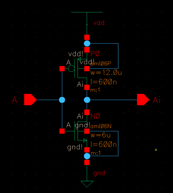
Tutorial 3 walks us through creating an inverter and simulating it. We begin with creating a schematic for the inverter.
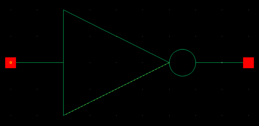
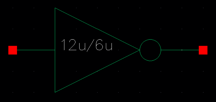
Then we generate a symbol from our schematic.
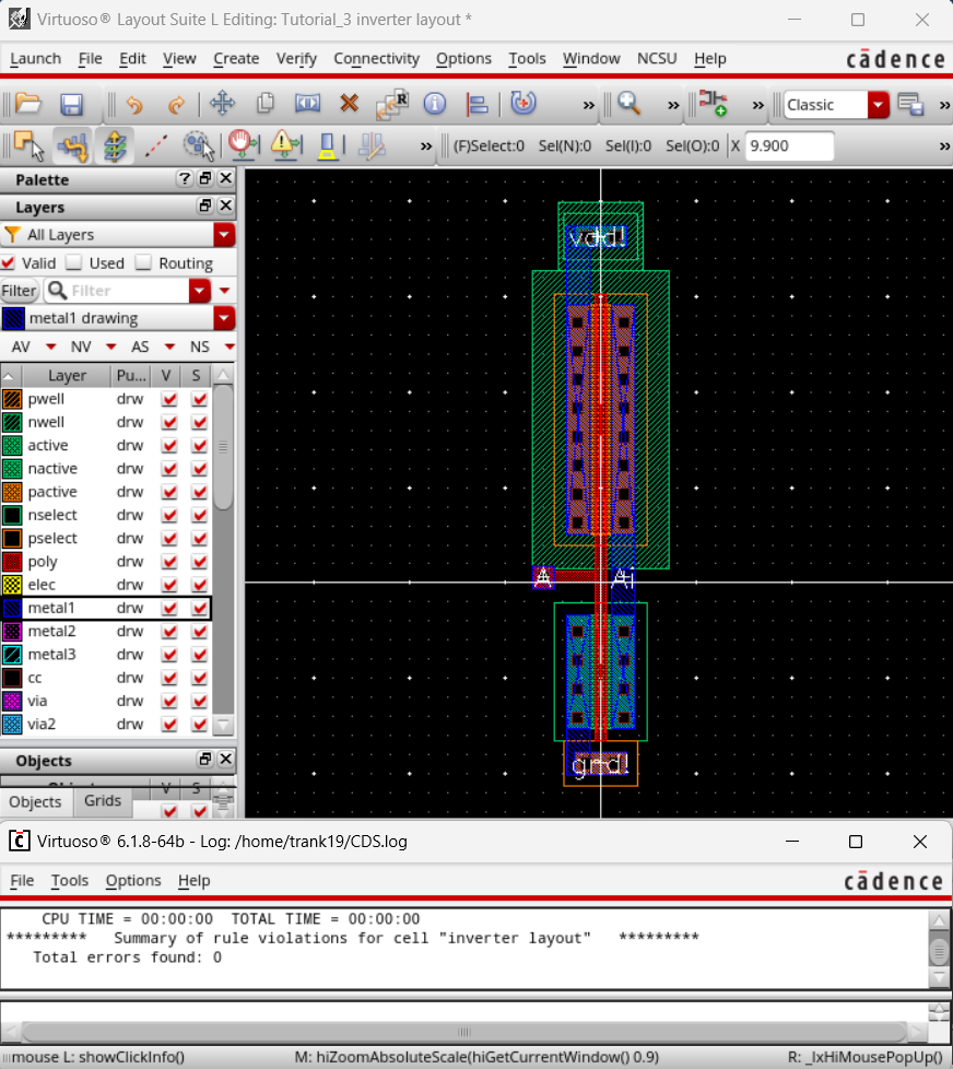
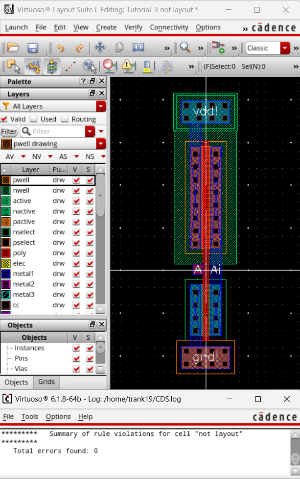
We then create a layout for our inverter and DRC.
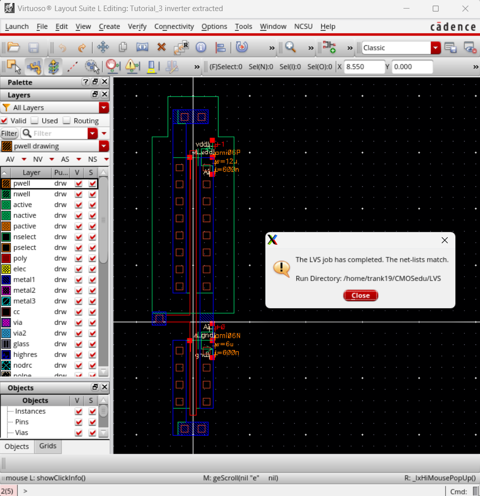
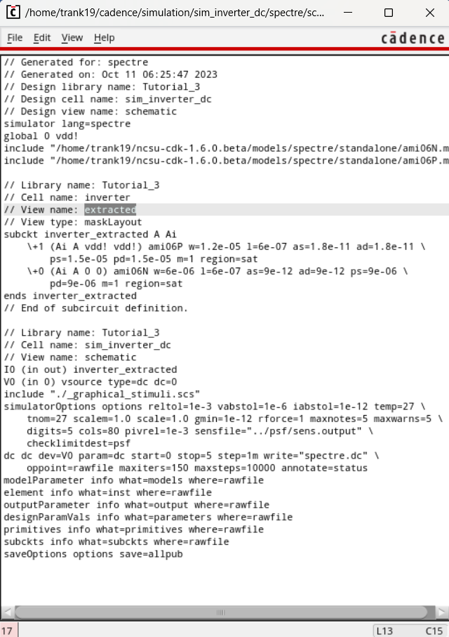
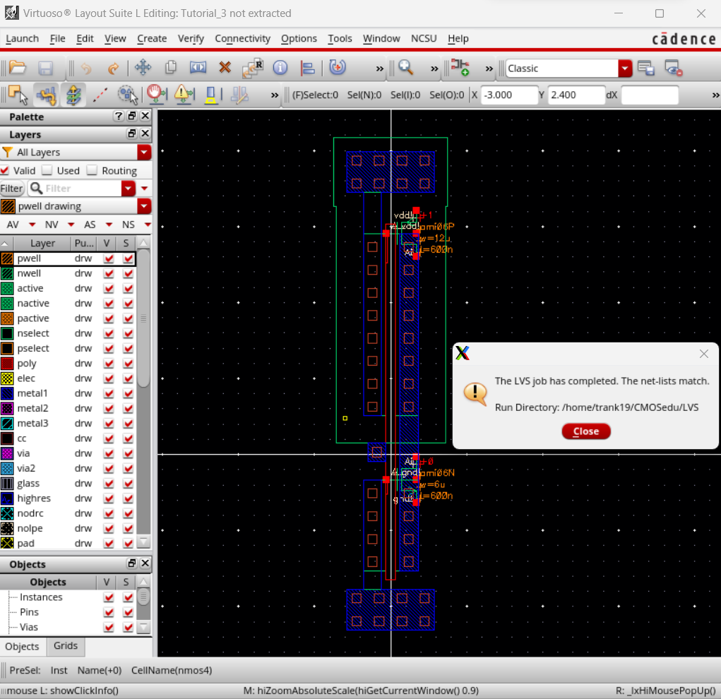
Now we can extract our layout and LVS verifying that the netlists match.
Now we can implement our inverter in a circuit for simulation.
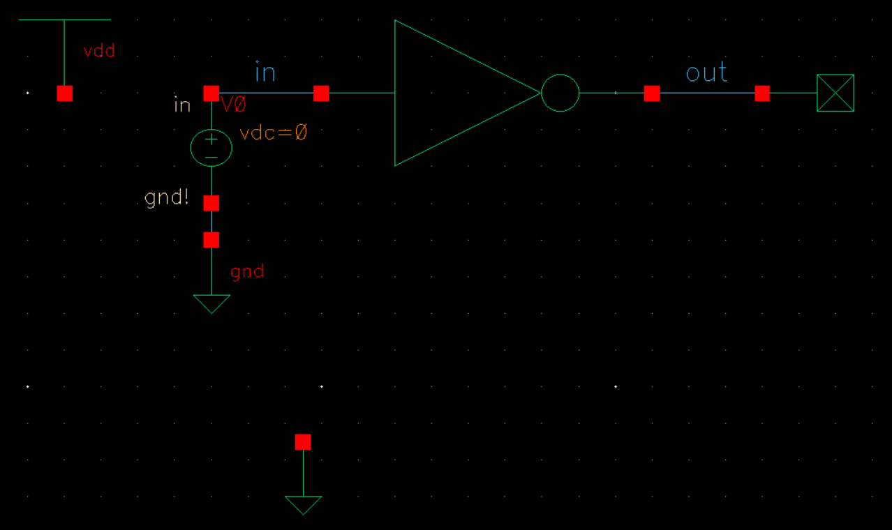
Our first simulation shows a circuit with no incoming voltage.
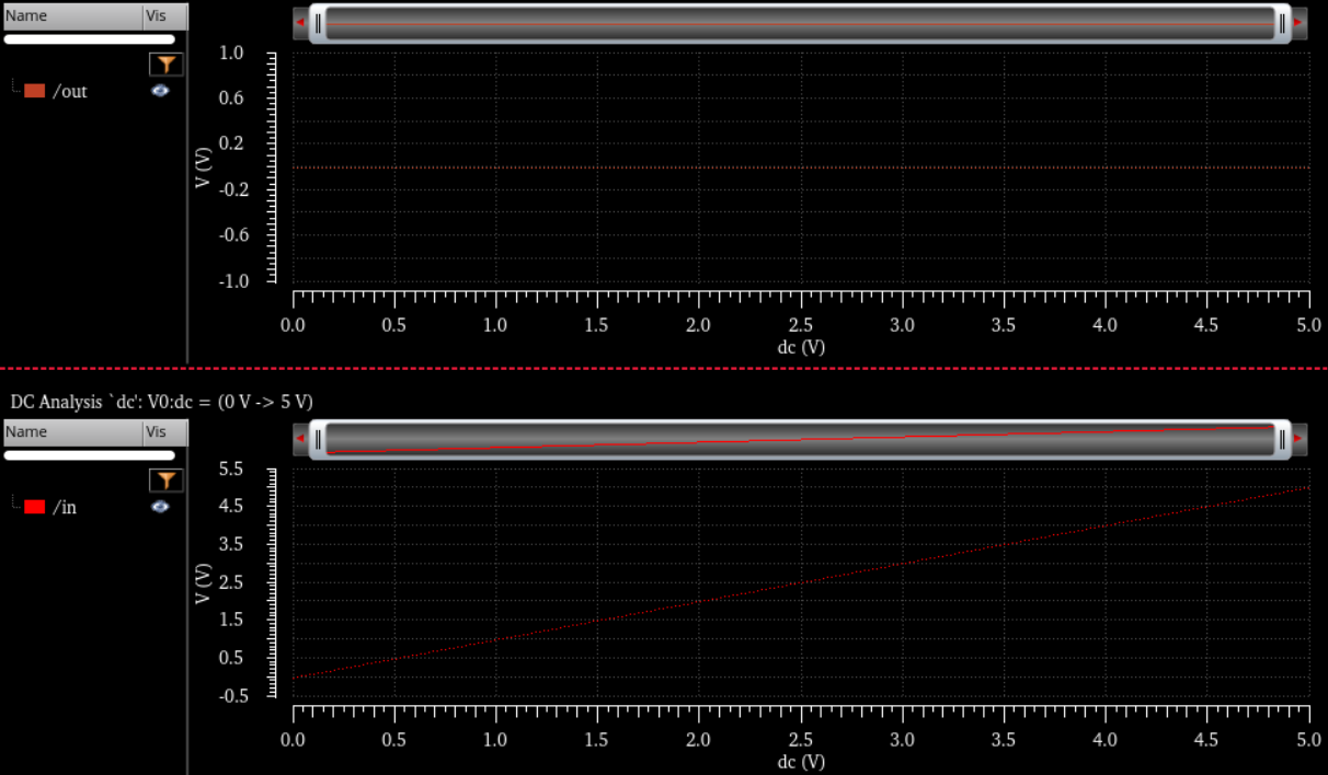
We then run the simulation again, but this time with a voltage and we get the following.
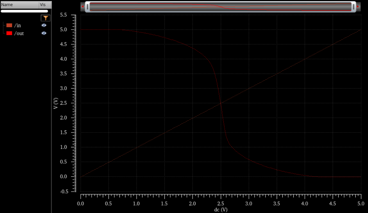
We again run another simulation with the extracted schematic and it gives us the same plot as above. We verify that we are looking at the extracted view through Simulations -> Netlist -> Display.
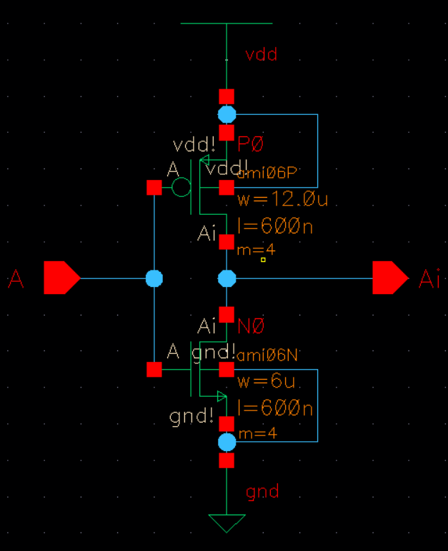
First we created a schematic for the 12u/6u inverter.
From the schmatic, we create a symbol for the inverter we just created.
We then create a layout and DRC.
Now we extract our layout and LVS verifying that the netlists match.
We will repeat the same process again, but this time we are creating a 48u/24u inverrter.
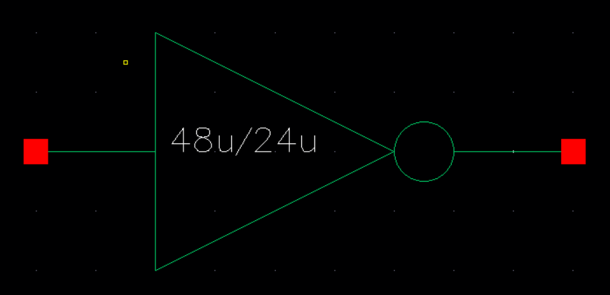
From our schematic, we generate a symbol.
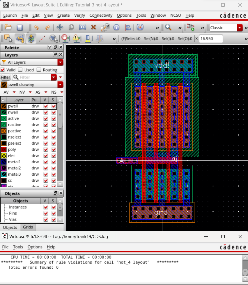
We then create a layout and DRC.
The next portion of this lab is to simulate the inverters we created. First, I made a circuit to simulate the 12u/6u inverter.
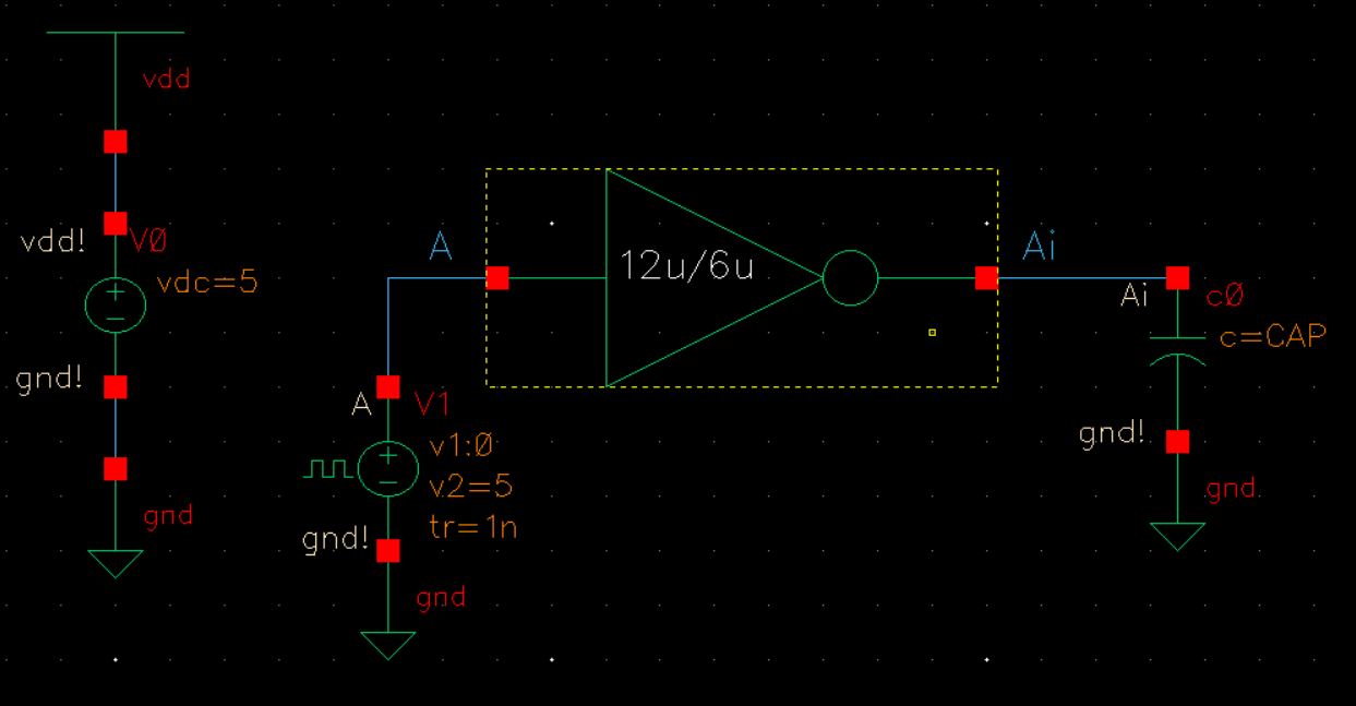
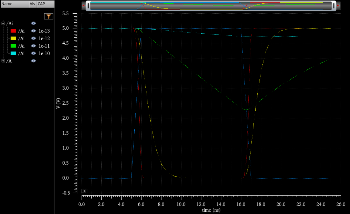
Using a parametric analysis sweep, I ran a spectre simulation at 100fF, 1pF, 10pF, and 100pF,.
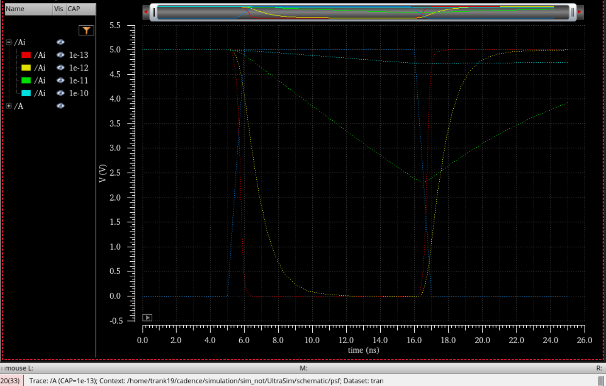
I then repeated my parametric sweep, but this time I simulated the circuit using UltraSim instead.
Another simulation circuit is created, but this time we use the 48u/24u inverter instead.
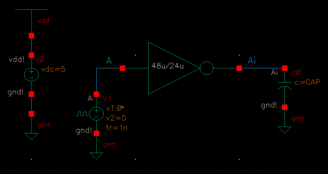
Once again, I simulate the same set of capacitance using a parametric analysis sweep.
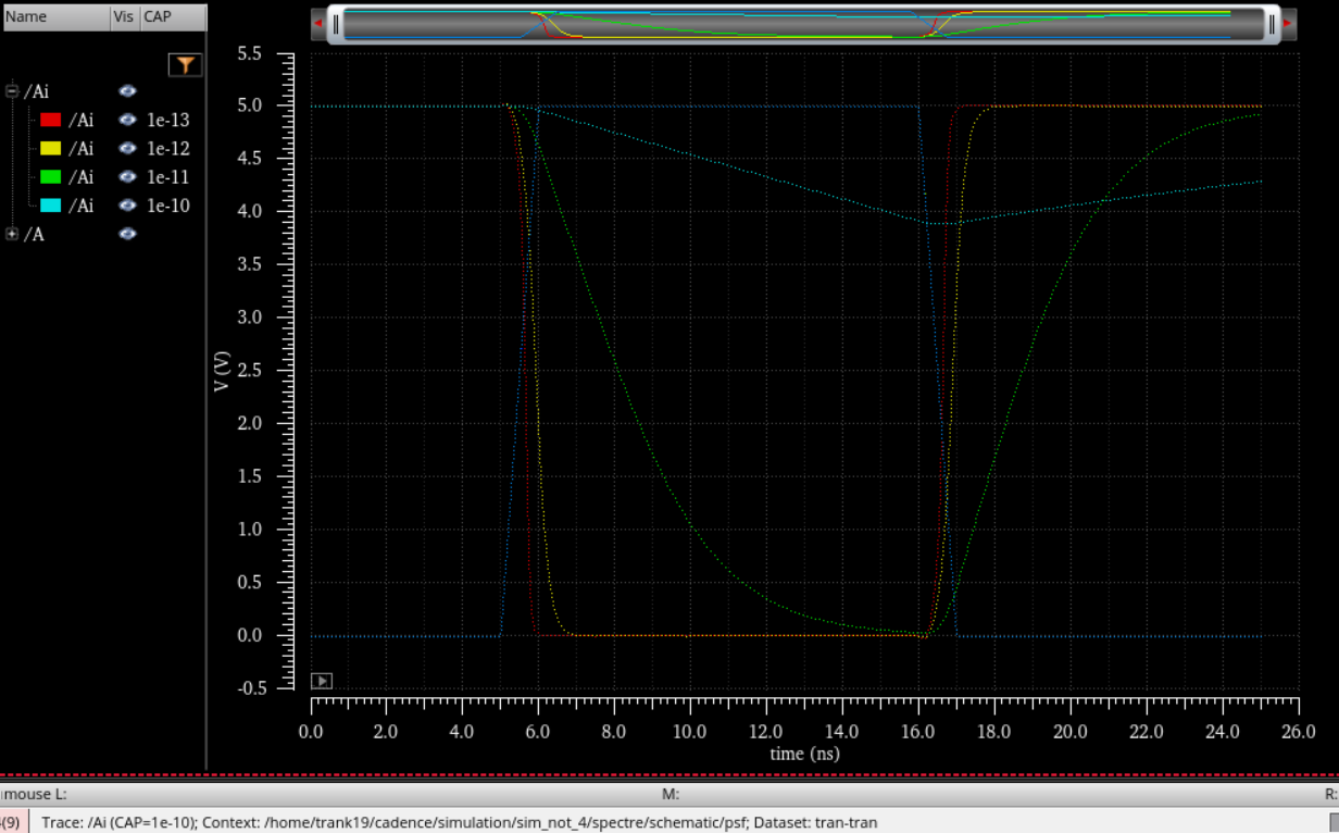
At the conclusion of this lab, we can see that the higher capacitance on the load results in a slower transition on the output. The 48u/24u inverter has a faster output transition due to its lower resistance which is a result of its larger size. The 12u/6u inverter has a slower output transition due to a higher resistance from its smaller relative size. One thing to note from this lab though was that UltraSim simulations actually took more time to run than the spectre simulations despite it being supposedly faster with decreased accuracy.
My Cadence files can be downloaded here: lab5_kt.zip
I then zipped my files and emailed myself a backup.