Lab 5 - EE 421L
Authored
by Adrian Lopez-Macuaran,
lopezmac@unlv.nevada.edu
September 24, 2021
Lab
description
This lab will focus on the desing, layout, and simulaitons of two different size inverters.
Pre-Lab
- Back-up all of your work from the lab and the course.
- Go through Tutorial 3 seen here.
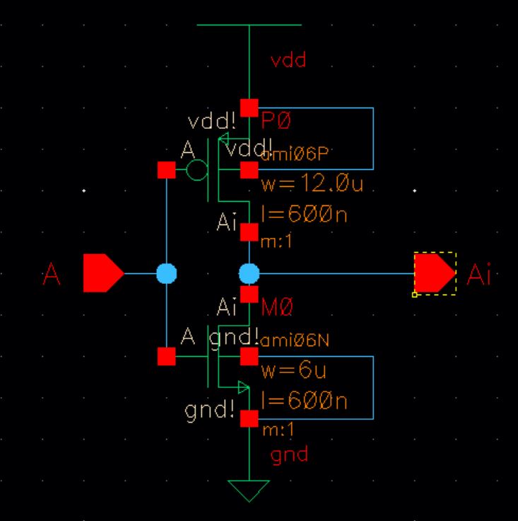
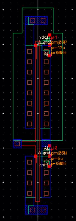
Following tutorial 3 we will design a schematic and layout of a 12u/600nm Inverter.

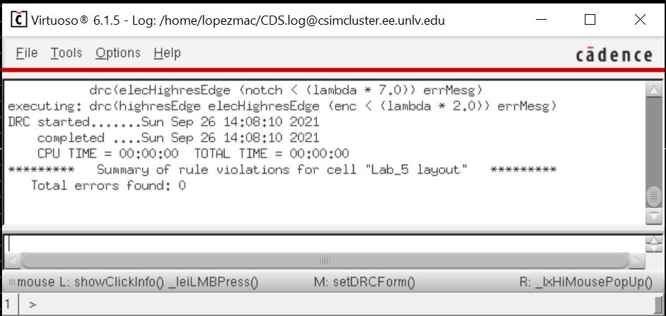
Next I will show my design has no errors when we run a DRC check.
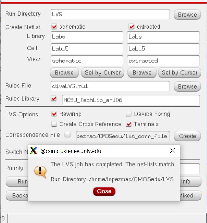
Next we will extract the layout run and LVS and make a symbol from our design.
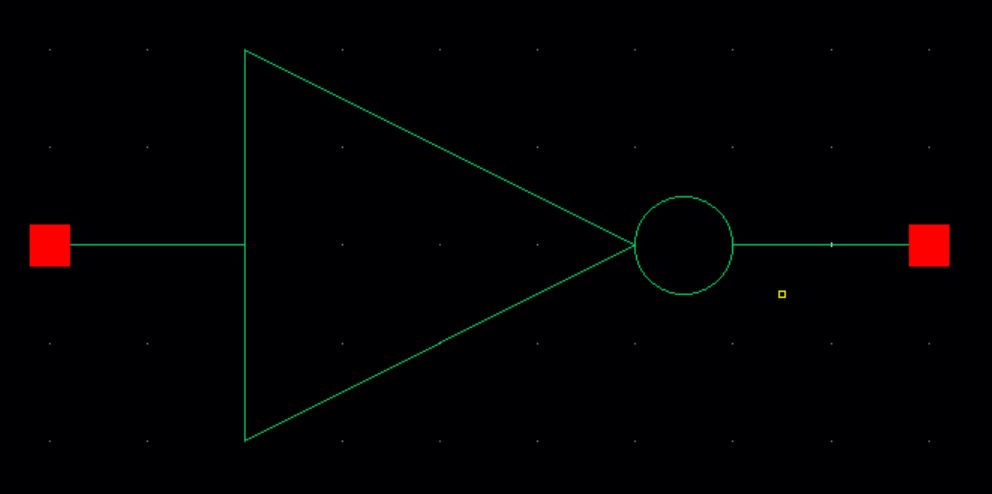
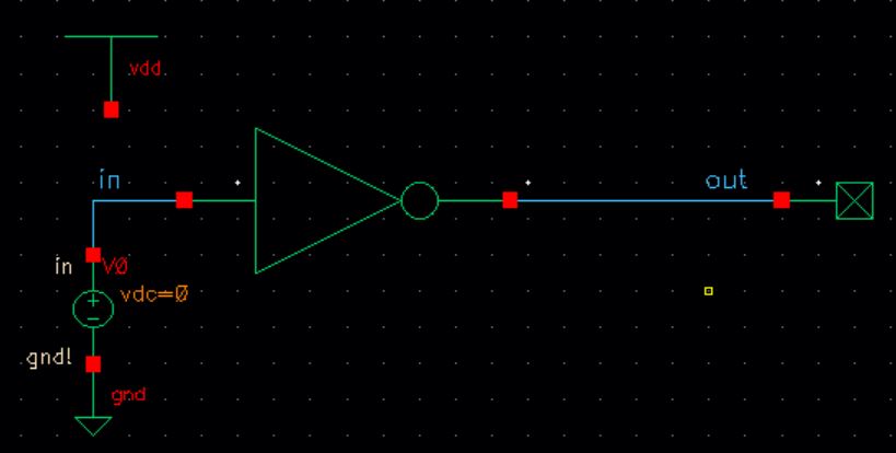
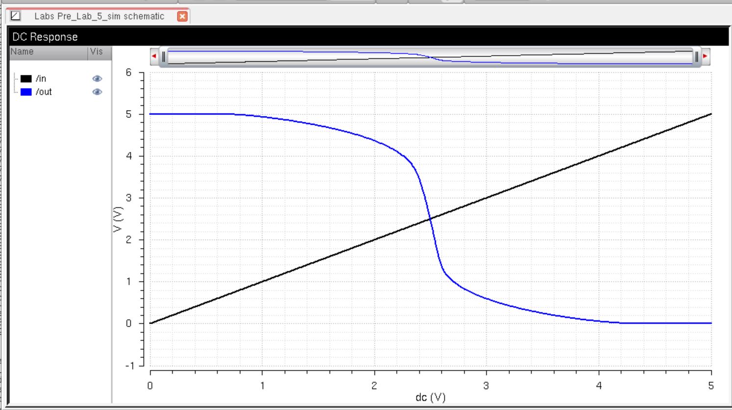
Finally to finish the prelab we will design a schematic and run a simulation of our inverter.
Lab Task
- Draft schematics, layouts, and symbols for two inverters having sizes of:
- 12u/6u (= width of the PMOS / width of the NMOS with both devices having minimum lengths of 0.6u)
- 48u/24u where the devices use a multiplier, M = 4 (set along with the width and length of the MOSFET
- Using SPICE simulate the operation of both of your inverters showing each driving a 100 fF, 1 pF, 10 pF, and 100 pF capacitive load
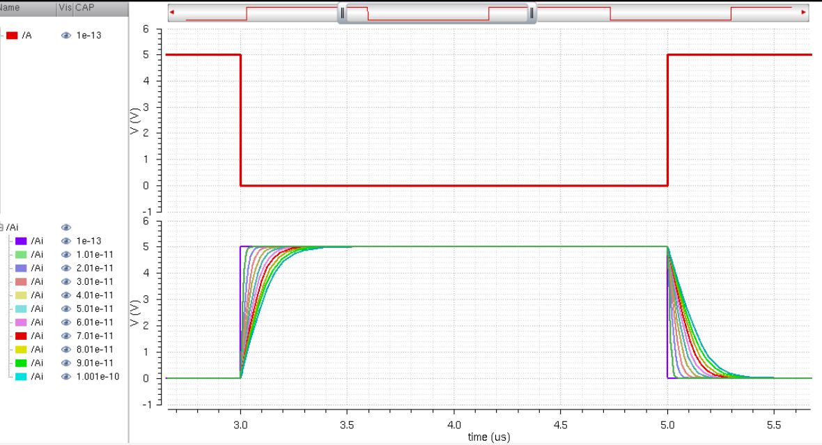
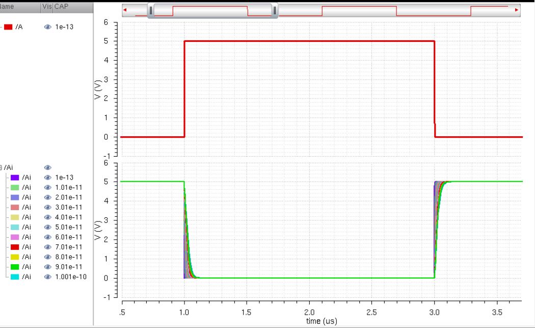
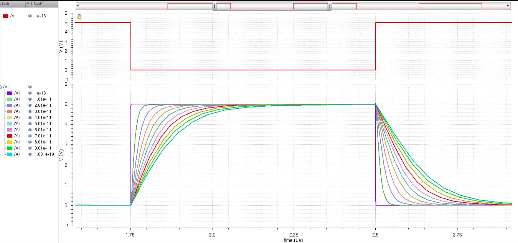
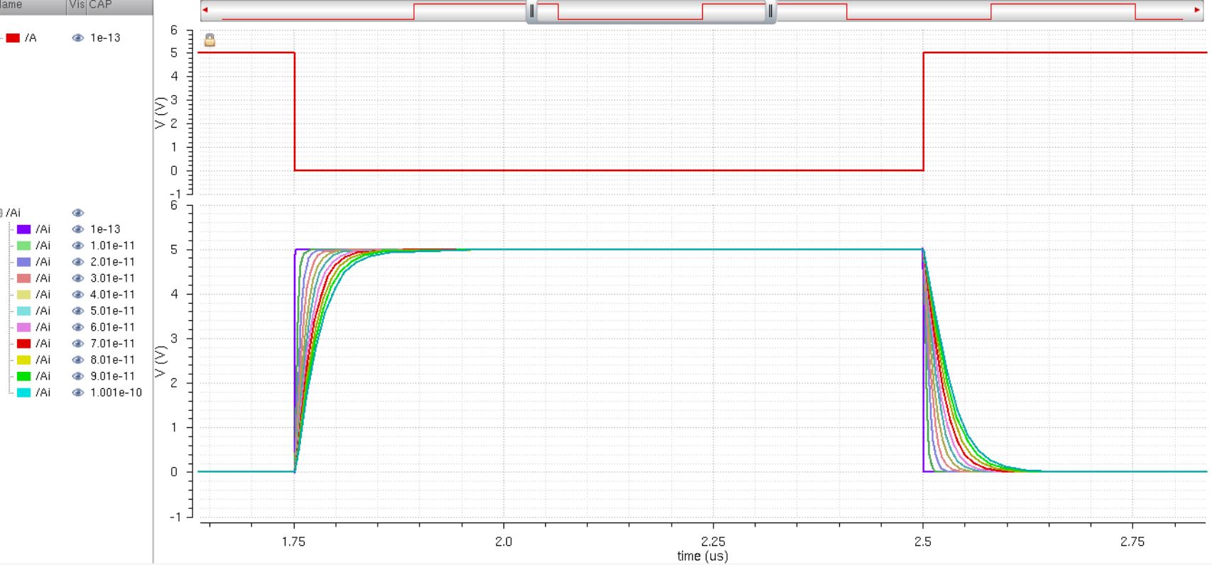
- Comment, in your report, on the results
- Use UltraSim (Cadence's fast SPICE simulator for larger circuits at the cost of accuracy) and repeat the above simulations
We start with the Schematic and layout of the 12u/0.6u inverter.
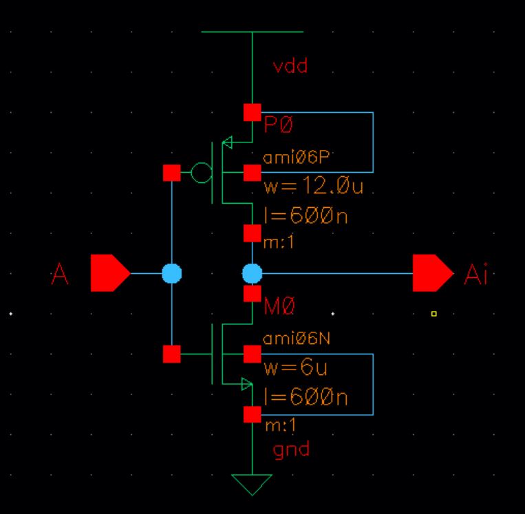

Next I will extract run and LVS check and create a symbol for our inverter.


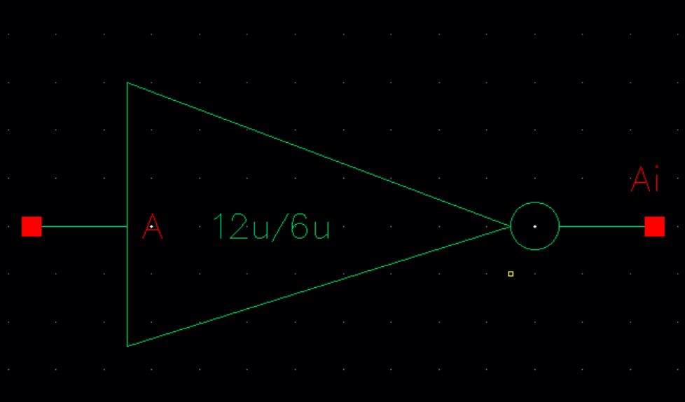
Next we will do the same as above, but for the 48u/24u Inverter.
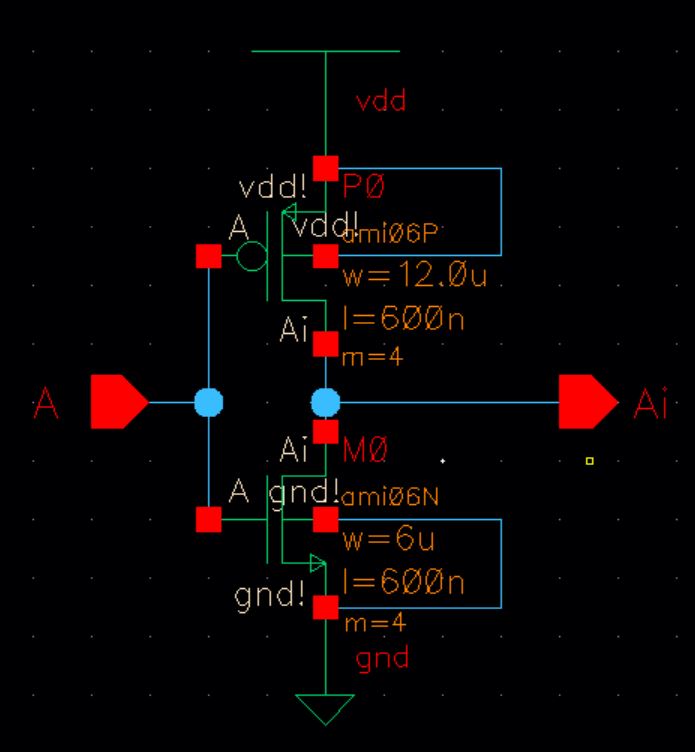
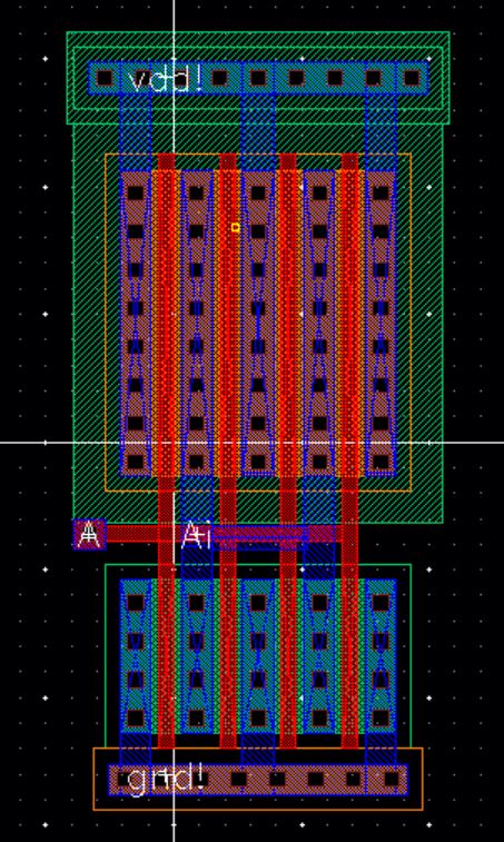
Next I will extract and run a LVS check and creat a symbol for our inverter.
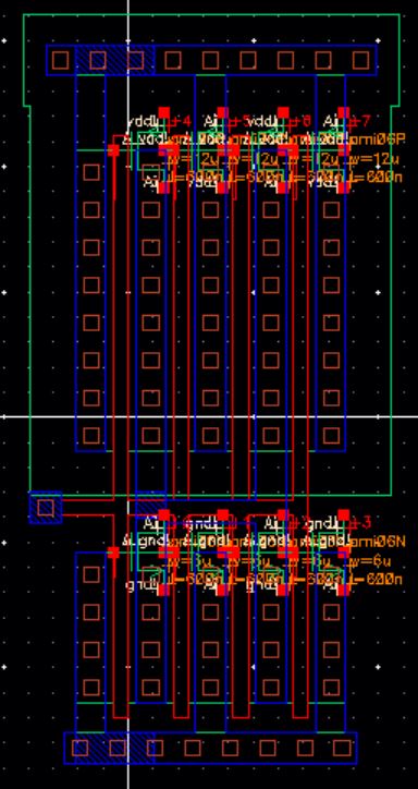
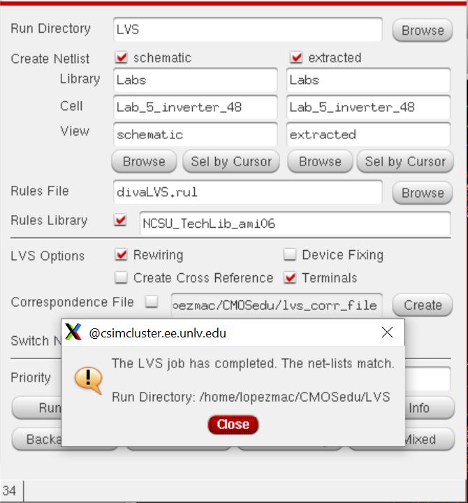
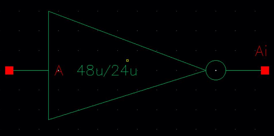
Next
is to design two schematics with our symobls and run simulaitons that
drive our capacitive load at varying capacitance. Each desing will run
5v to VDD and also use a pulsed input from 0 to 5v to test our desing.
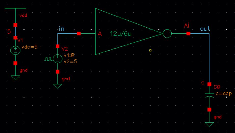
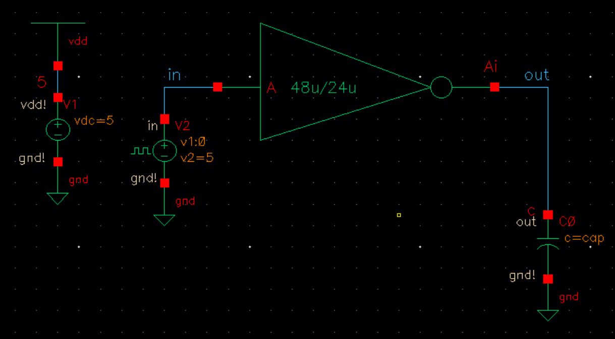
Before running simulations we have to set up the variable CAP and our parametric simulaiton parameters.

The first simulaitons are using SPICE each driving a 100 fF, 1 pF, 10 pF, and 100 pF capacitive load. First simulation is of the 12u/0.6u inverter
Next will be the simulation for the 48u/24u inverter.
Next we will repeat the simulations using UltraSim. First I will show the results of the 12u/0.6u inverter.
Next I will show the simulation results of the 48u/24u inverter.
Conclusion
After
finishing the lab and reflecting on the informaiton gathered I can see
that both devices performed similiar while the capacitance was low.
When the capacitance load is increased the inverter that best performs
is the 48u/24u inverter. I belive this is due to the extra fingers the
larger inverter has allows the MOSFET to charge an discharge the
capacitor more efficiently.
Backing up work
As always my work was backed up twice.


Return to Labs