Lab 5 - ECE 421L
Lab Description
The purpose of this week's lab is to design CMOS inverters.
A CMOS inverter can be created using an NMOS and PMOS MOSFETs.
For the lab, we created two inverters. One with a 48µm width PMOS
and 24µm width NMOS, and one with a 12µm width PMOS and a 6µm width NMOS.
The length for all four MOSFET was 600nm.
The inverters are simulated for the output voltage driving capacitive loads. Simulations were done for each
inverter driving 100fF, 1pF, 10pF, and 100pF loads. The simulations were done using both
the spectre simulator and the UltraSim simulator.
Prelab
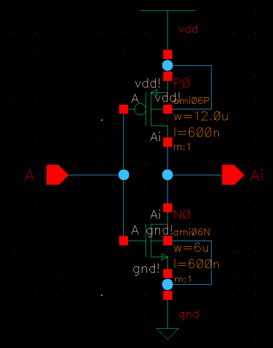
The pre-lab follows tutorial 3, and follows the creation of the 12µm/6µm NMOS/PMOS width
inverter. Here is the schematic view of the inverter.
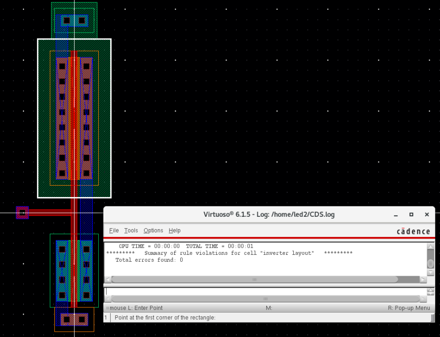
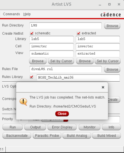
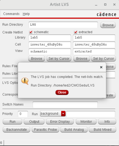
I then created a layout with properly labeled pins so that the schematic can be LVS'd.
Lab
48µm/24µm Inverter:
The inverter is drafted similar to how the 12µm/6µm inverter is. Here is the schematic (Notice the multiplier).
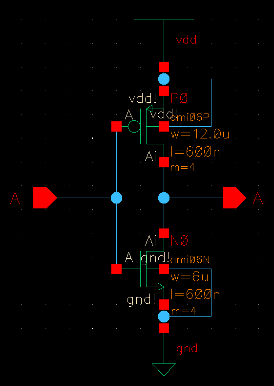
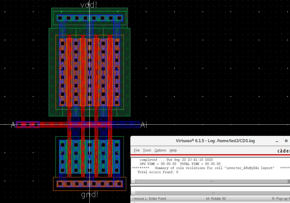
Here is the layout. Because a 48µm wide PMOS is impractical, a 4 finger PMOS was used.
Simulations:
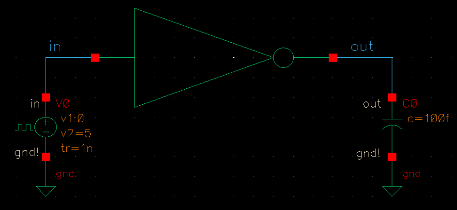
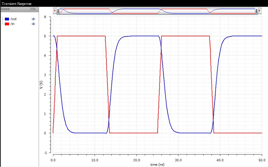
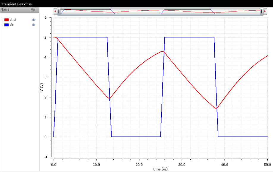
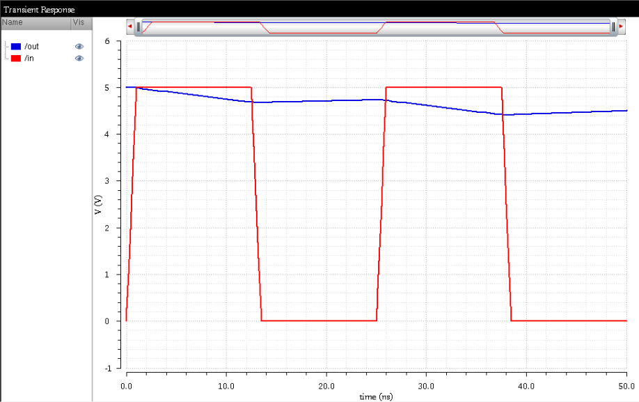
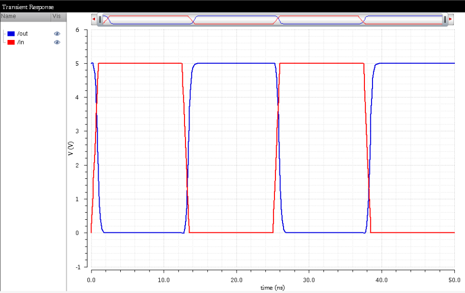
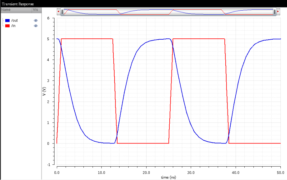
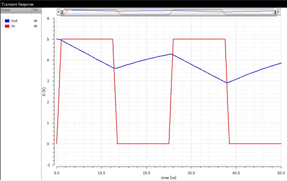
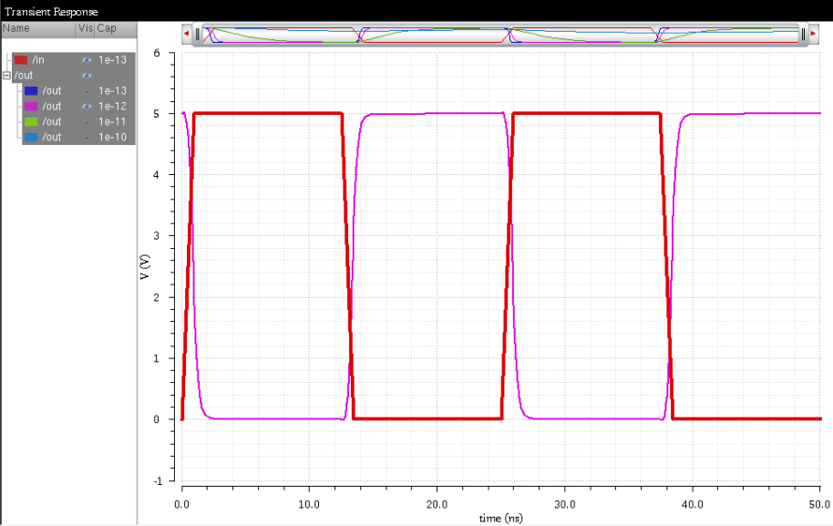
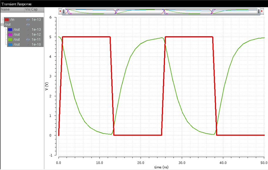
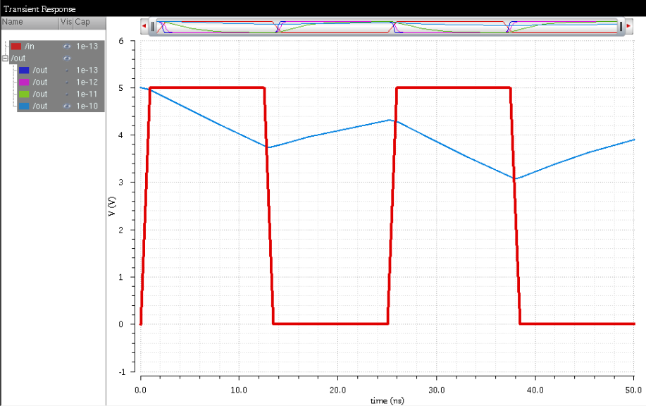
Next the inverters are simulated while driving capacitive loads of 100fF, 1pF, 10pF, and 100pF.
Here, the spectre simulator is used. This is the test schematic used for all of the simuations.
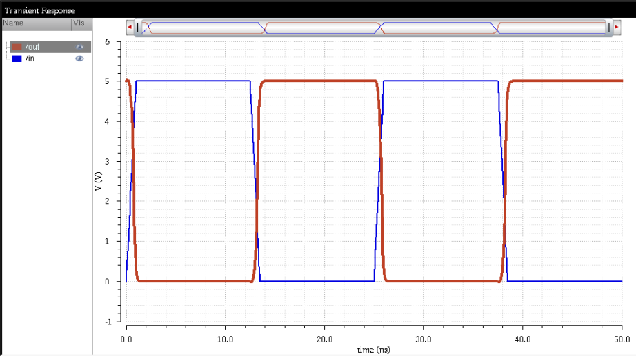
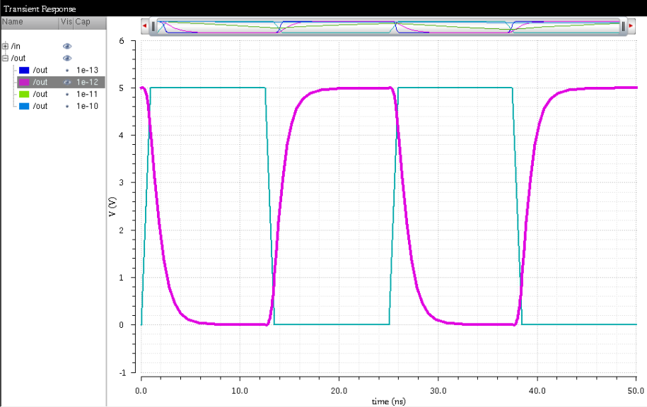
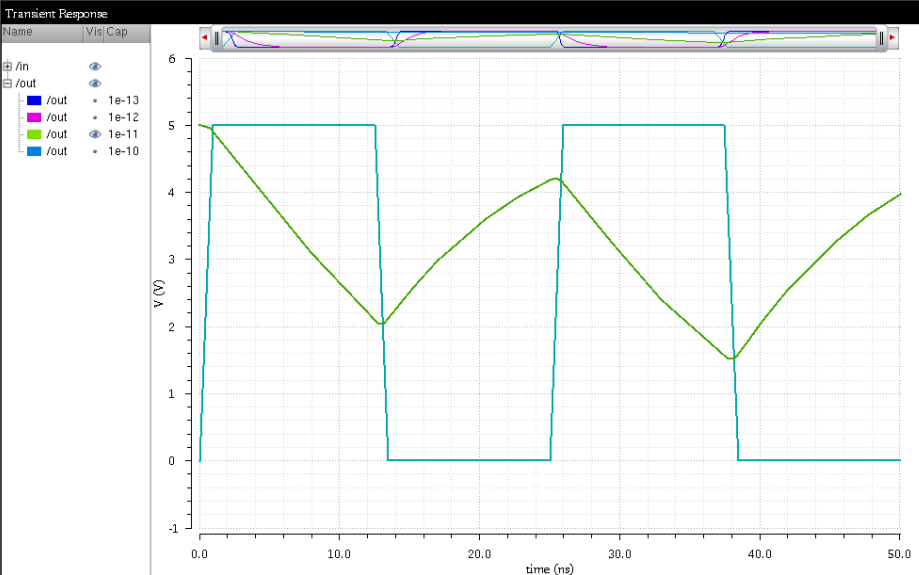
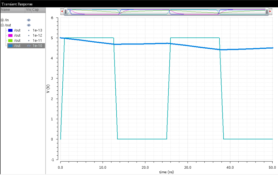
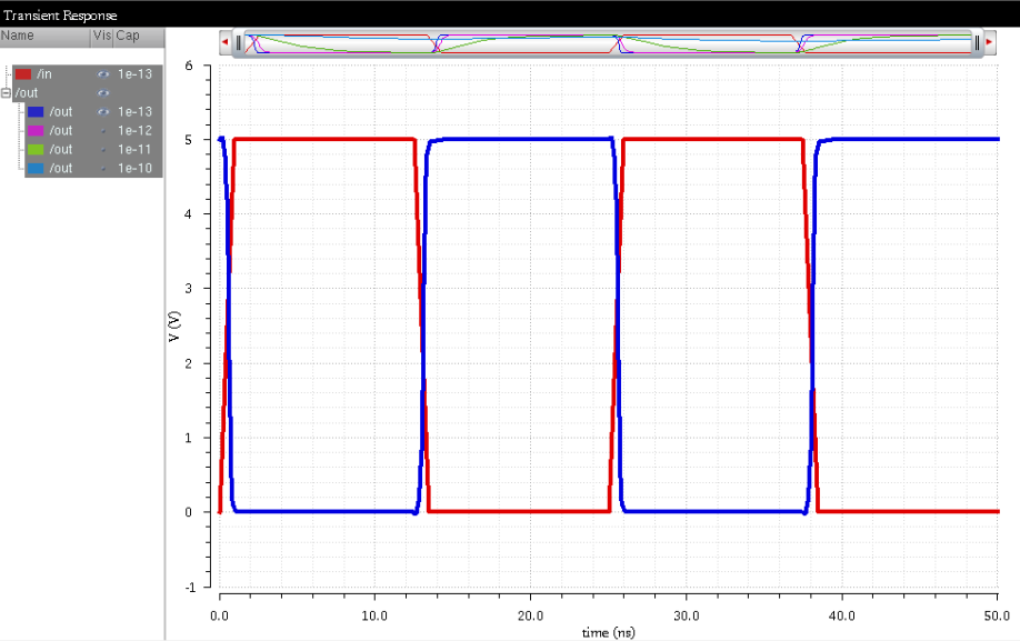
These are the results showing the 100fF, 1pF, 10pF, and 100pF simulations
respective from left to right and top to bottom.
Spectre Simulation:
12µm/6µm:
48µm/24µm:
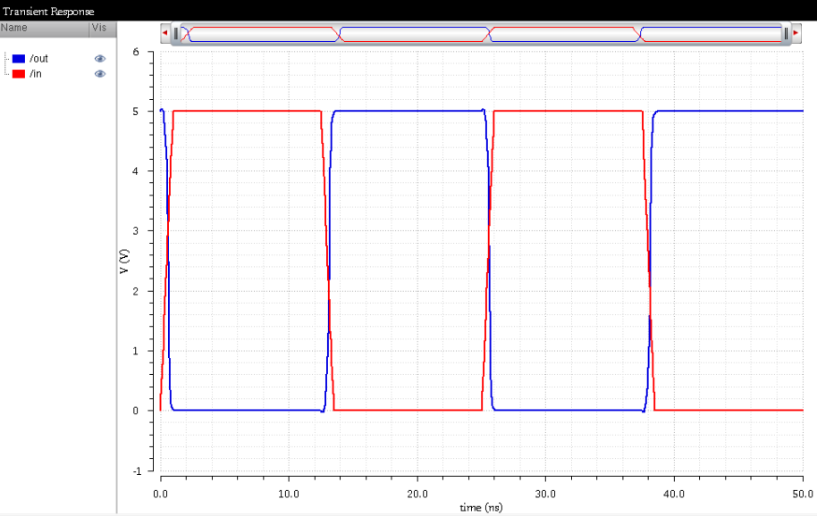
UltraSim Simulation:
Next, the simulations were repeated using UltraSim.
12µm/6µm:
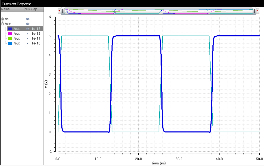
48µm/24µm:
Results:
Looking at the results of the simulation, it can be noted that the 48µm/24µm takes a shorter amount of time to reach 5V than
the 12µm/6µm. This is likely because the wider MOSFETs have a lower resistance, attributed to it's wider channel.
As a result, the RC time constant is lower for the wider MOSFETs, allowing them to switch faster.
Files:
The cells done in this lab can be found here: lab5_dvl.zip.
That concludes lab 5.