Lab 1 - ECE 421L
Elizabeth Baldivias
baldivi3@unlv.nevada.edu
September 7, 2014
This first lab will go through the first part of Tutorial 1 seen here. In Tutorial 1 a voltage divider was created and simulated on cadence.
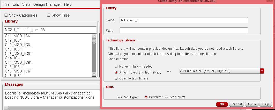
In
the first step a new library was created by going to Library Manager
-> File -> New -> Library. This new library was named
"Tutorial_1" and the "AMI 0.6u C5N process" was attached.
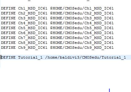
Once the new library was added I verified that it was added to the cds.lib file.
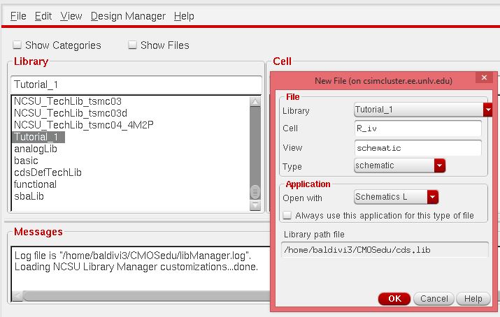
Now, to create a new cell I went to File -> New -> Cell View and created a new cell named "R_div" with a schematic view.
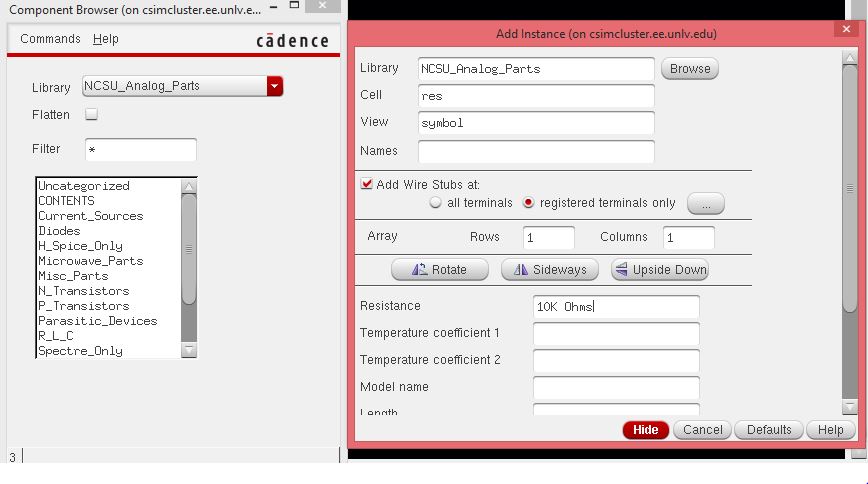
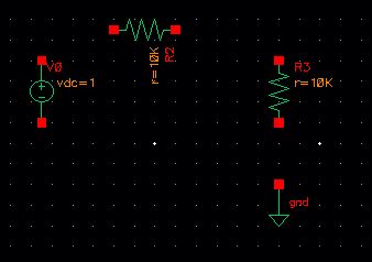
Once
this was created, I could start adding components. To create a new
compenent I pressed the bindkey "i" . Which brought up an "Add
instance" window. In that window I clicked on "Browse" and a "Component
Browser" window came up. In that window I selected the
"NCSU_Analong_Parts" folder and found a resistor "res" and gave it a
10k value.
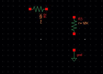
Once I created this resistor, I placed two of them onto the schematic.
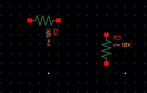
Next a ground had to be added. I found gnd by going to NCSU_Analog_Parts->Supply Nets->gnd.
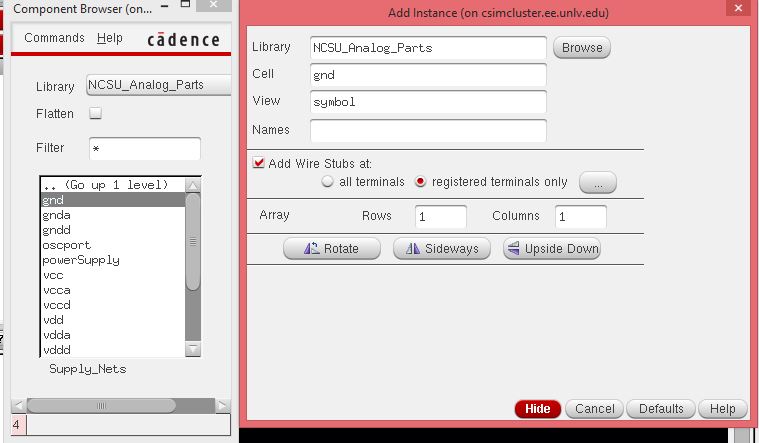
After I created the part, I placed it on the schematic.
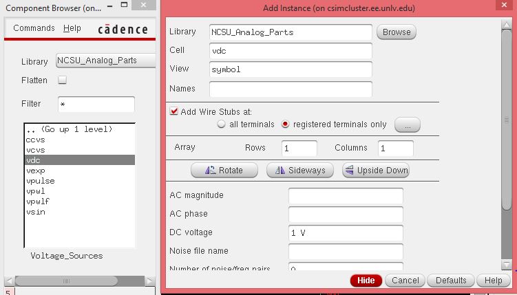
The
next part to create was a voltage source. I found that part by browsing
and going to NSCU_Analog_Parts->Voltage Sources->vdc. I set the
voltage source to 1V.
After creating the voltage source, I placed it onto the schematic.
With
all the parts placed, all that was needed to do was wire them together.
By pressing the bindkey "w" it will create a wire to place.
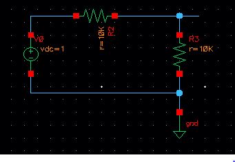
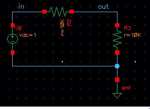
All
that was left to do was label the wires "in" and "out". That was done
by pressing the bindkey "l" and clicking on vin, and naming it "in".
The same was done for vout and naming it "out".
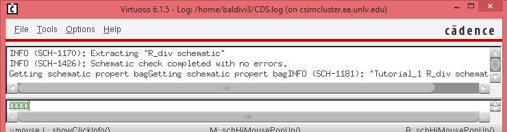
Before
simulating, I had to "Check and Save" my work to see if there were any
errors. As seen below the check went through without any errors.
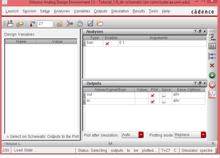
To
simulate with Spectre, I had to go to Launch->ADE L . This brings up
the "Virtuoso Analog Design" window. Here I went to Analyses->
Choose and selected "tran" for transient analysis with a stop time of 1
second. I also needed to select the outputs that I wanted to plot. I
went to Outputs->To Be Plotted->Select on Schematic and selected
"in" and "out" on my voltage divider schematic. Now the analog design
window looked like the image below.
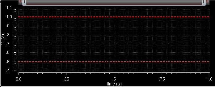
With everything set then I clicked the green button and ran the simulation. This was the resulting output.
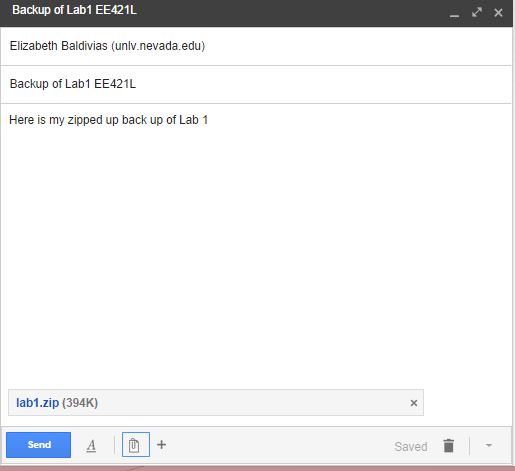
While working on our labs, we should be making regular back ups of what we are working on. I zipped my lab1 folder up.
Then, I emailed it to myself, and received it.
Return to baldiv3 labs here.