Lab 6 - ECE 421L
Authored
by Michael Kajkowski,
10/13/2013
kajkowsk@unlv.nevada.edu
For this lab we will designing CMOS nand, nor & xor logic gates, as well as a full adder.
We will be designing these circuits in schematic and layout cells. And finally
we will simulate our circuits (Using Spice & IRSIM). For this lab we will use layouts from other labs
to make the work easier. Remember to perform DRC, ERC & NCC often & backup all of your work!
First we will make a nand gate
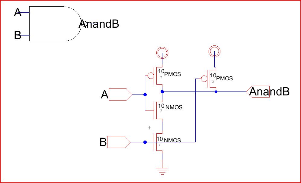
You will want to use the inverter from last lab. Make the connections as seen above. Export the off page
nodes. We will use 10/2 for both PMOS and NMOS (Remember to label the transistors using the
set spice model). To make the icon use splines, you will need to select the spline and hit "y" so you can reshape
the curves.
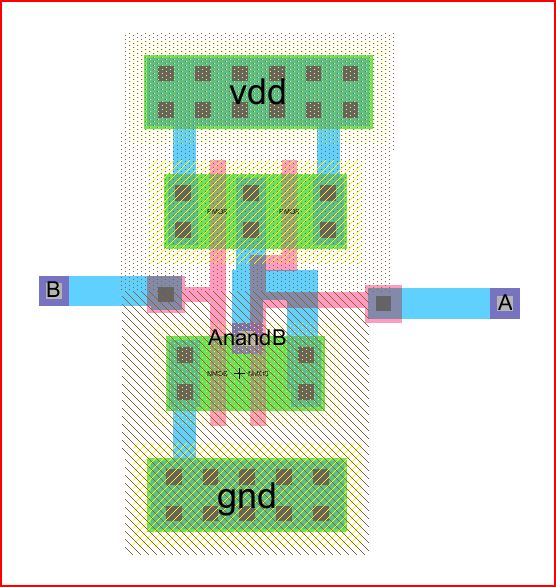
The layout should look like....
Lets simulate....
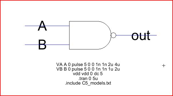
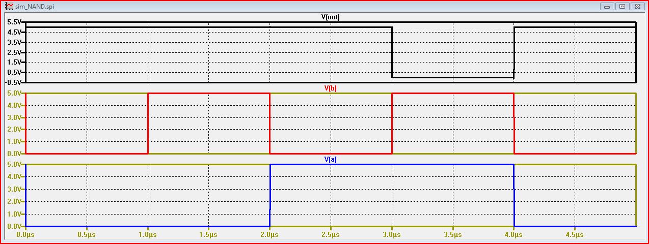
Spice:
IRSIM:
You can use the logic gate chart to verify these results. ( 1 1 will result in 0, all other combinations
will result in 1).
Now for the NOR gate:
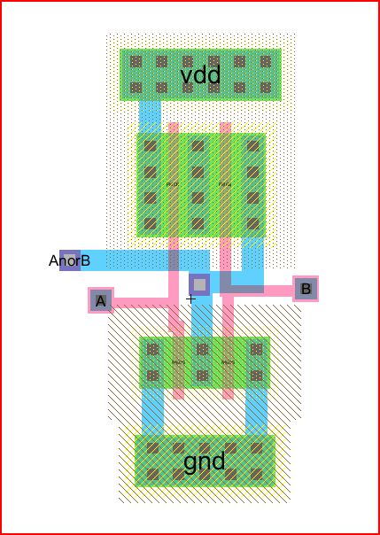
NOR layout:
Simulations...
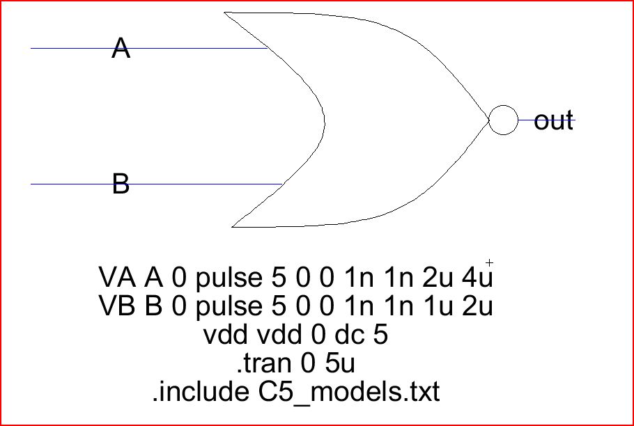
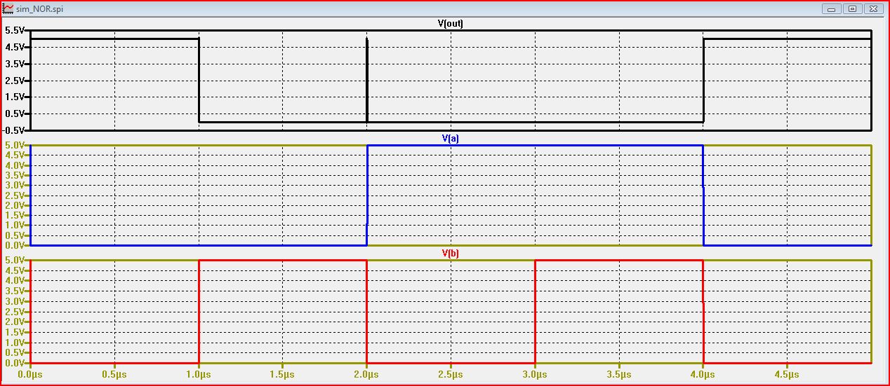
Spice:
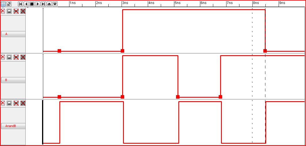
IRSIM:
(The NOR gate results in a 1 when outputs are 0, everything else is one).
Finally the XOR gate:
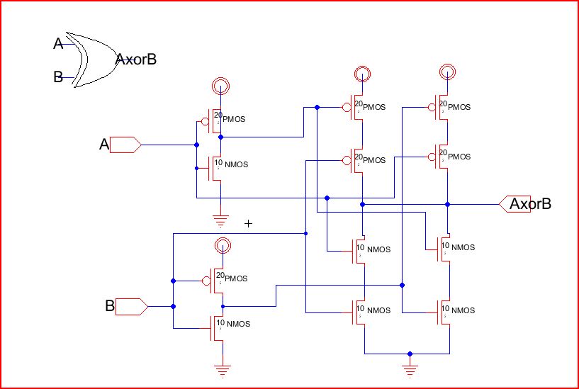
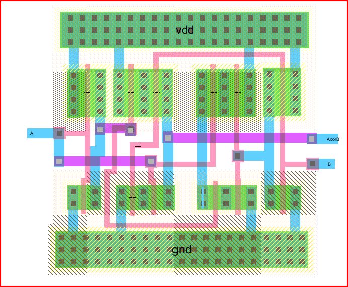
XOR layout:
Simulations...
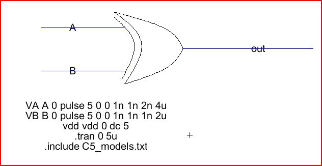
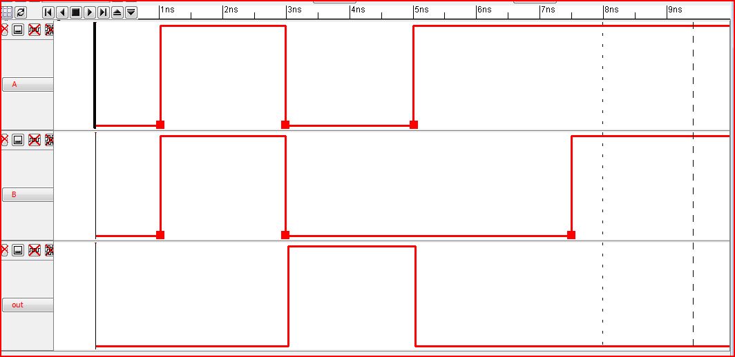
Spice:
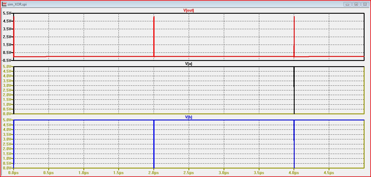
IRSIM:
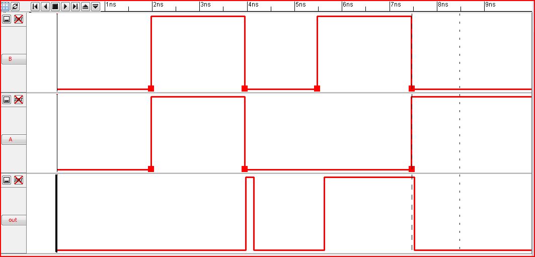
(The XOR gate results in a one when the two outputs are different, and zero when they are the same).
Now that we have completed making our gates, we can now use them to build a full adder.
We will make one with two nand's, one nor, two xor's, and three inverters. We will
then make a second full adder but using three nand's and two xor's. For each full adder be sure
to make icons to run the simulations. We will run Spice and IRSIM simulations.
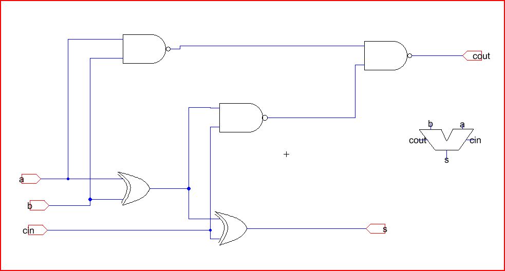
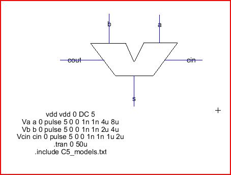
First full adder:
Using the icons from the gates we made, we can construct this circuit seen above. Again, use splines
to make your icon.
Simulations...
Spice:
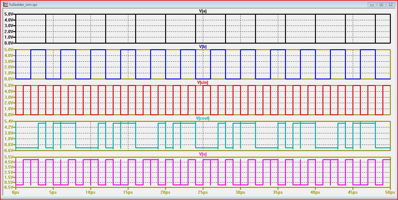
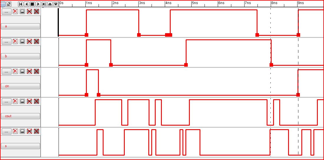
IRSIM:
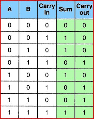
Here is a sample truth table for a full adder...
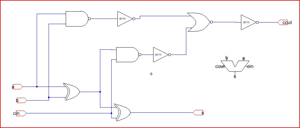
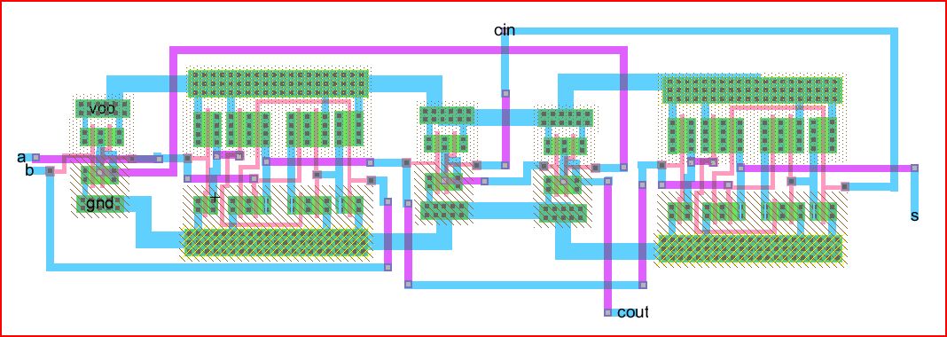
Second full adder:
Notice that we are now using three nand gates and two xor gates.
Layout:
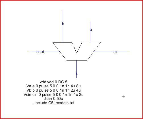
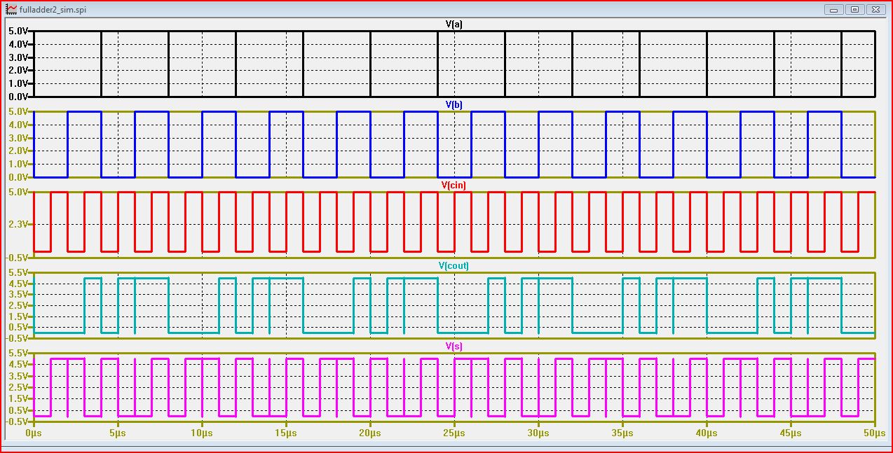
Simulations...
Spice:
IRSIM:
REMEMBER TO BACKUP ALL OF YOUR WORK!!!
My jelib file
Return to labs...