|
EE 420L |
|
AUTHOR: Henry
Mesa |
|
Laboratory Overview: This
laboratory regards the review of basic Operational Amplifier topologies;
while, introducing new non-ideal op-amps, finite gain, and offset. In this
lab we utilize the LM324 op-amp. (LM324.pfd) |
|
Procedure: The LM324 is exclusively used throughout this
laboratory. For oscilloscope images, assume the yellow signal to be the input
and blue signal for the output. For the following experiments
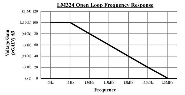
assume VCC+ = +5V and VCC- = 0V. Gain-Bandwidth of the LM324:
|
|
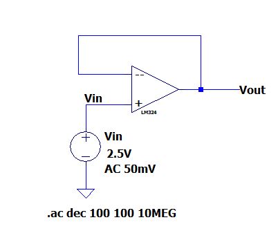
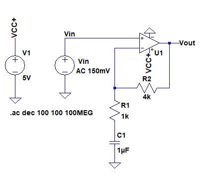
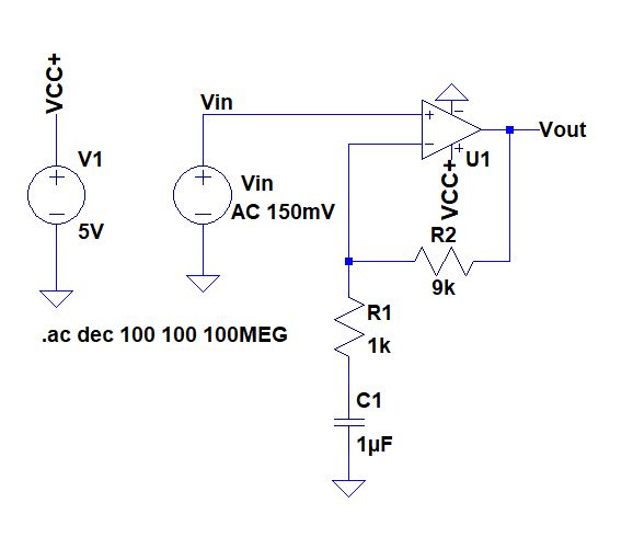
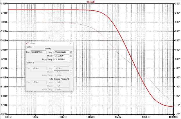
Experiment 1: Estimate, using the
datasheet, the bandwidths for non-inverting op-amp topologies having gains of
1, 5, and 10. Circuit
1:
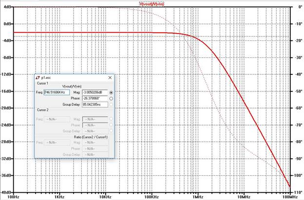
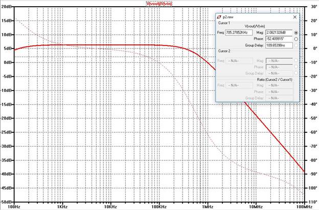
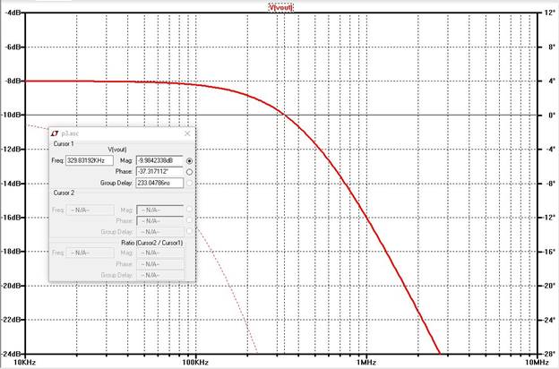
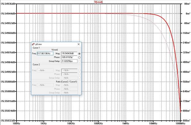
Experimental
Results:
Simulation:
|
|
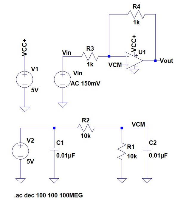
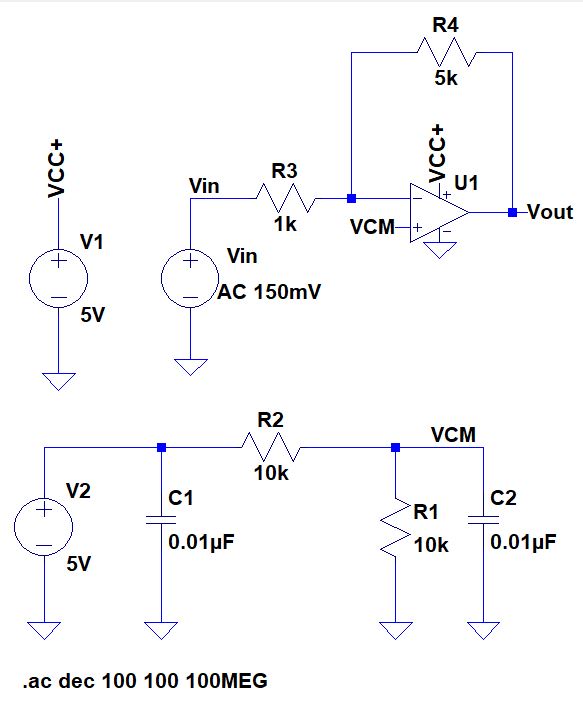
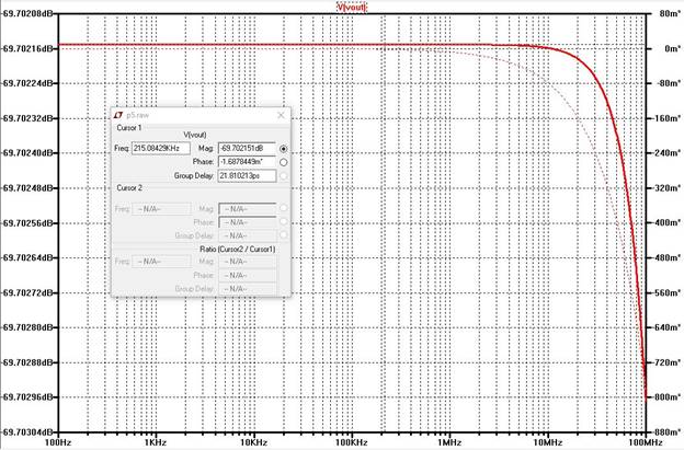
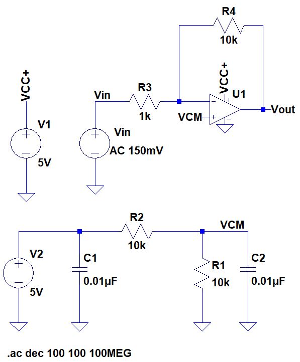
Experiment 2: Estimate, using the
datasheet, the bandwidths using the inverting op-amp topology having
gains of -1, -5, and -10.
Circuit
4:
|
|
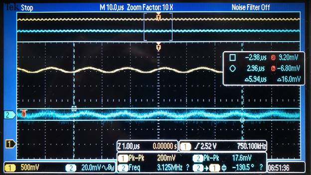
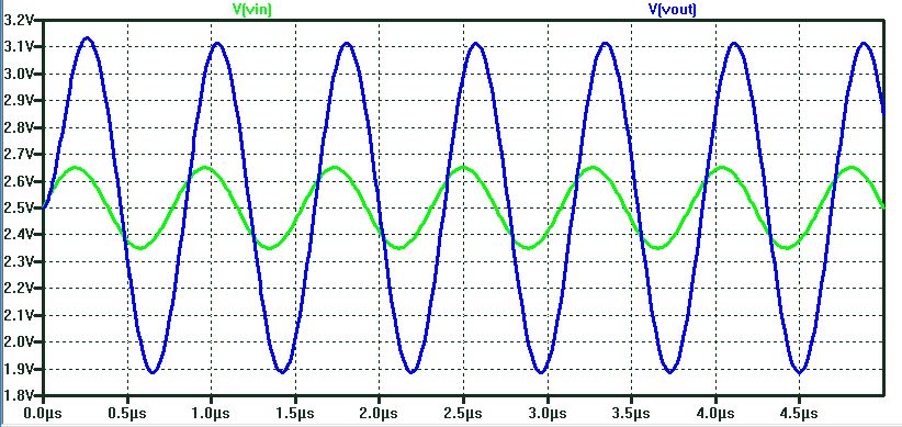
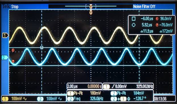
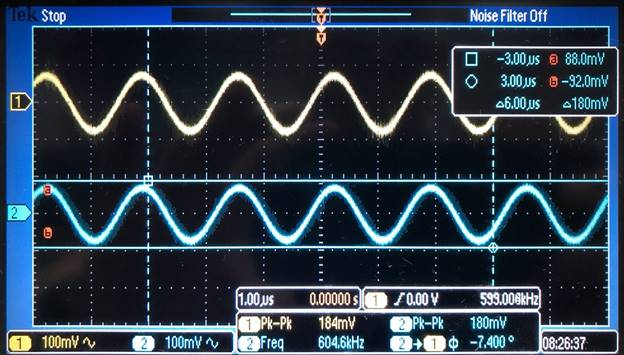
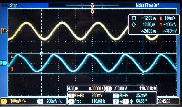
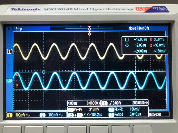
Slew Rate with Sinusoid Vsignal Input: we see on the first picture bellow
that the slew rate is not huge factor at lower frequencies (10kHz). When
using higher frequencies, the slew rate has to be taken into consideration.
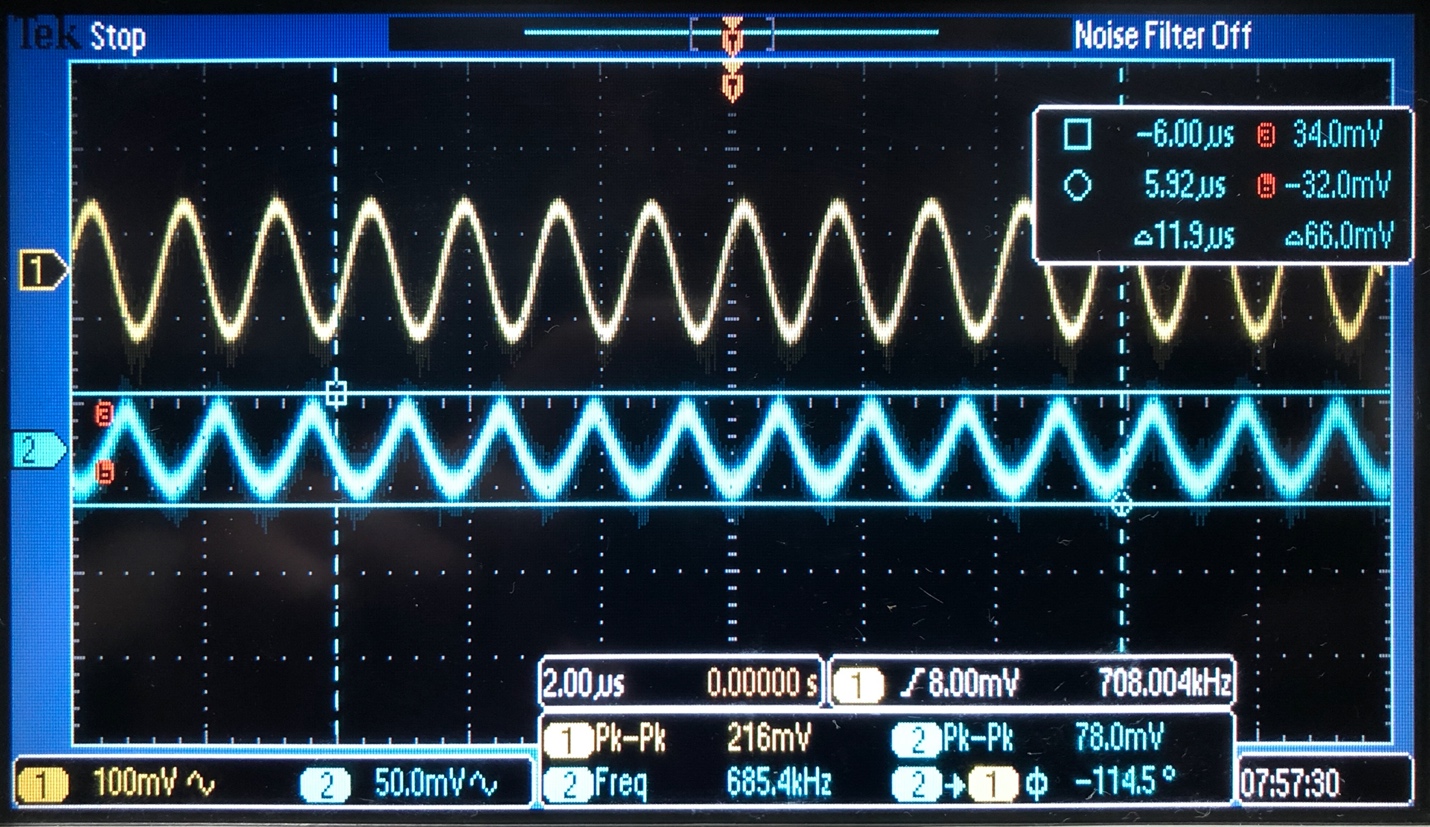
We can calculate the slew rate by using the cursor measurements in picture 2.
Experimental
Results:
Picture 1.
Picture 2.
Slew Rate = 180mV/24µs = 7.5mV/µs |
|
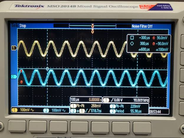
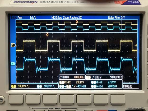
Slew Rate with Pulse Vsignal Input: we see on the first picture bellow that
the slew rate is not huge factor at lower frequencies (10kHz). When using
higher frequencies, the slew rate has to be taken into consideration. We can
calculate the slew rate by using the cursor measurements in picture 2. Experimental
Results:
Picture 1.
Picture 2.
Slew Rate = 272mV/20.02µs = 13.6mV/µs |