 Lab 9 – EE 420L
Authored by: Daniel Senda
Email: sendad1@unlv.nevada.edu
Spring 2019
Due: 04-24-2019
1) Introduction
This lab
introduces students to the process of designing a Beta-Multiplier Reference (BMR).
The students are required to make use of CMOS transistor arrays in the
CD4007/CD4007UB chip to make implement the design.
2) Pre-Lab Description
The pre-lab
required the student to complete the following procedures before proceeding
with the lab:
- Lab 9 made use of the level=1 MOSFET
model created in lab 8 and, again, the MOSFETs in the CD4007UB chip.
- Design and simulate the operation of
a Beta-Multiplier Reference (BMR) that biases the NMOS devices so that they have
a gm of 20 uA/V
o
Use
a simple (big) resistor to VDD for the start-up circuit (explain how the
addition of a resistor ensures start-up).
o
When
the BMR is operating the current in the big resistor should be much smaller
than the current flowing in each branch of the BMR
- Write-up, like a homework assignment,
your design calculations and simulation results.
3) Description of Lab
Procedures
Lab 9
instructs the student to utilize the CD4007 chip. Due to no availability of the
CD4007 chip, the professor let the students utilize the CD4007UB chip instead.
It was also required that the chips be from the same production lot. The reason
is to ensure that using a BMR to bias a current mirror is possible. Otherwise
the chips will not “match” and the current mirrors will not be possible.
The first
part of the lab instructed the students to build the BMR design from the
pre-lab and characterize it experimentally.
The student
used CMOSedu book formulas to solve for a resistance
for the circuit.
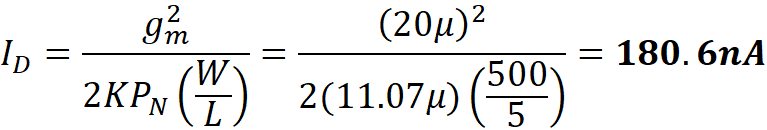
Solving for ID
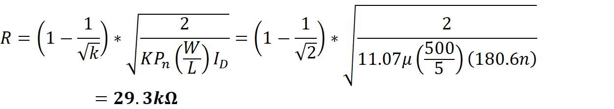
Next, using the value ID to solve for the value of R
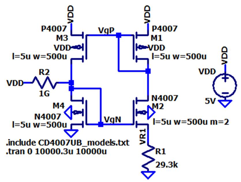
A start-up
circuit is necessary to get the circuit going and operate correctly. The method
that was used was adding a 1G ohm resistor from VDD to a branch of the BMR
circuit seen below. This creates about 5nA current going into the branch to
start it up but is a small enough current to keep the BMR stable.
LTspice BMR Schematic:
LTspice .tran simulation results:
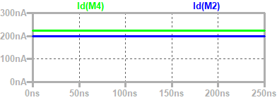
As can be noted, the currents in the BMR are around 200nA which is what the
student was aiming for.
Next, the
student DC swept the VDD voltge source from 0V to 10V
with 0.1V increments.
LTspice .dc simulation results for VgN and VgP:
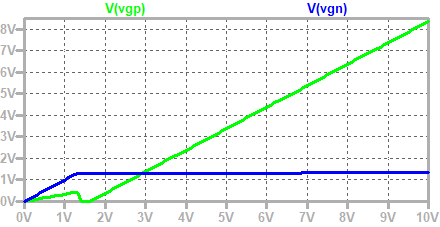
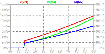
LTspice .dc
simulation results for ID
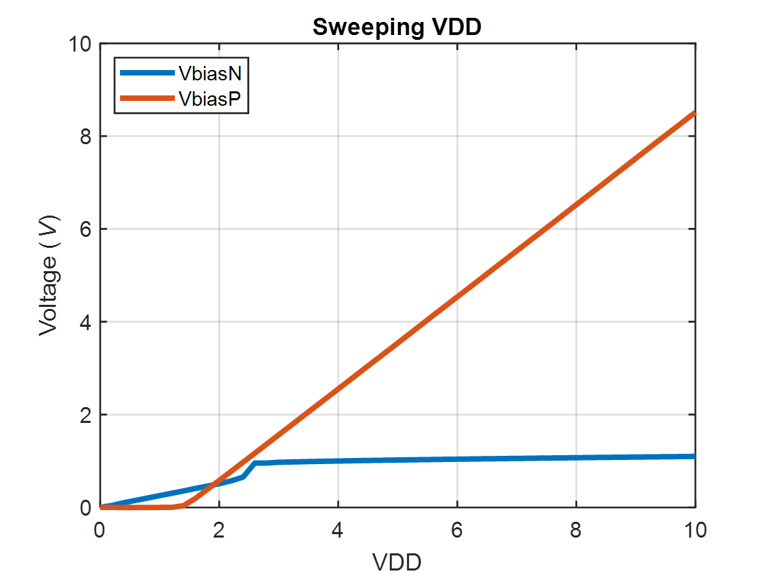
The students
then built the BMR circuit on a bread board and did an experimental DC sweep by
varying the voltage of the power supply. The values were recorded, and the data
was used to create the plots in MATLAB.
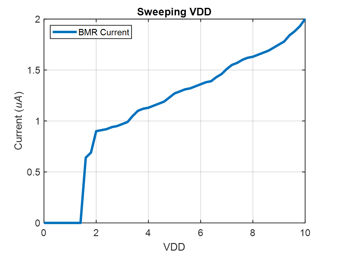
The results
the student got for the current were off by about a factor of 3. This could be
due to parasitic factors that were not considered.
Following
the characterization of the BMR the students were required to build current
mirrors.
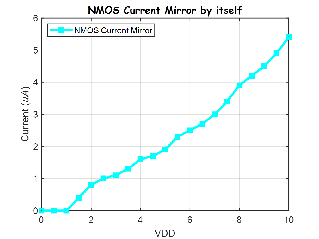
The student built an NMOS current mirror
and measured the current of the NMOS mirror as VDD was swept from 0 to 10V.
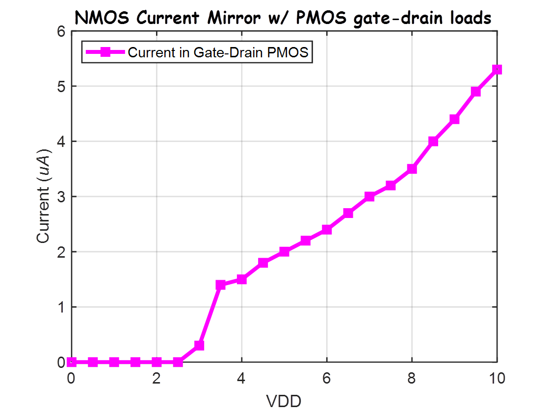
The student then used the NMOS
current mirror to drive two PMOS devices and also
measured the current.
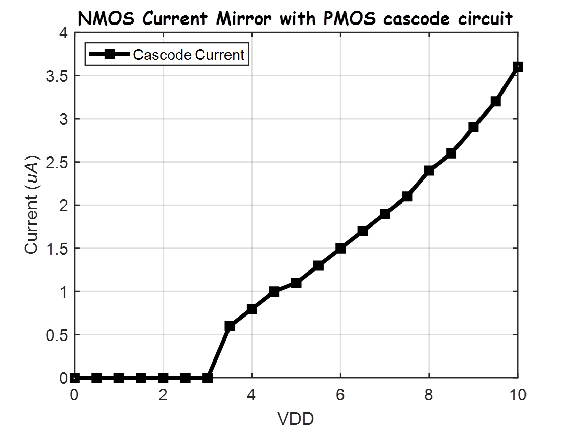
Lastly, the student used the NMOS
current mirror to drive a cascade PMOS circuit and measured the current.
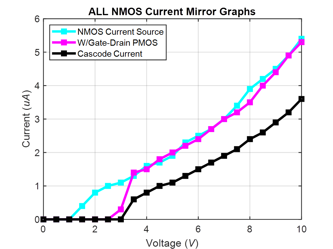
The student then put the plots all on
one graph to be able to compare the differences in currents from the different
NMOS current mirror configurations.
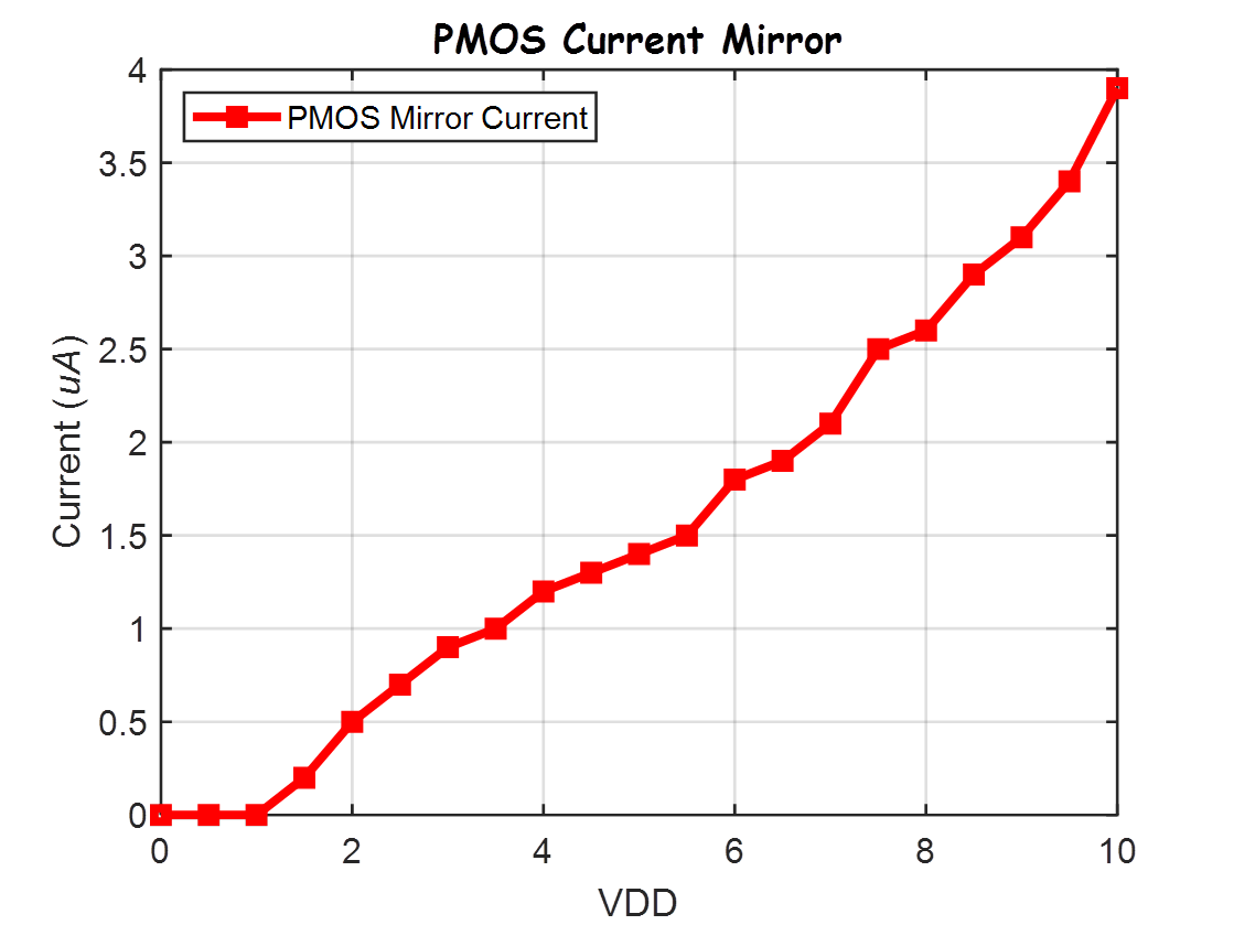
PMOS Current Mirror:
The student
built a PMOS current mirror and measured the current of the PMOS mirror as VDD
was swept from 0 to 10V.
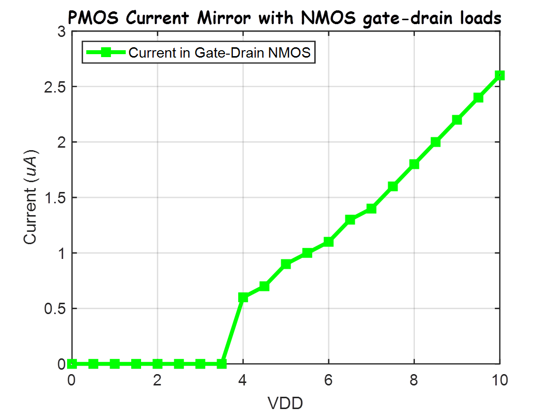
The student
then used the PMOS current mirror to drive two NMOS devices and
also measured the current.
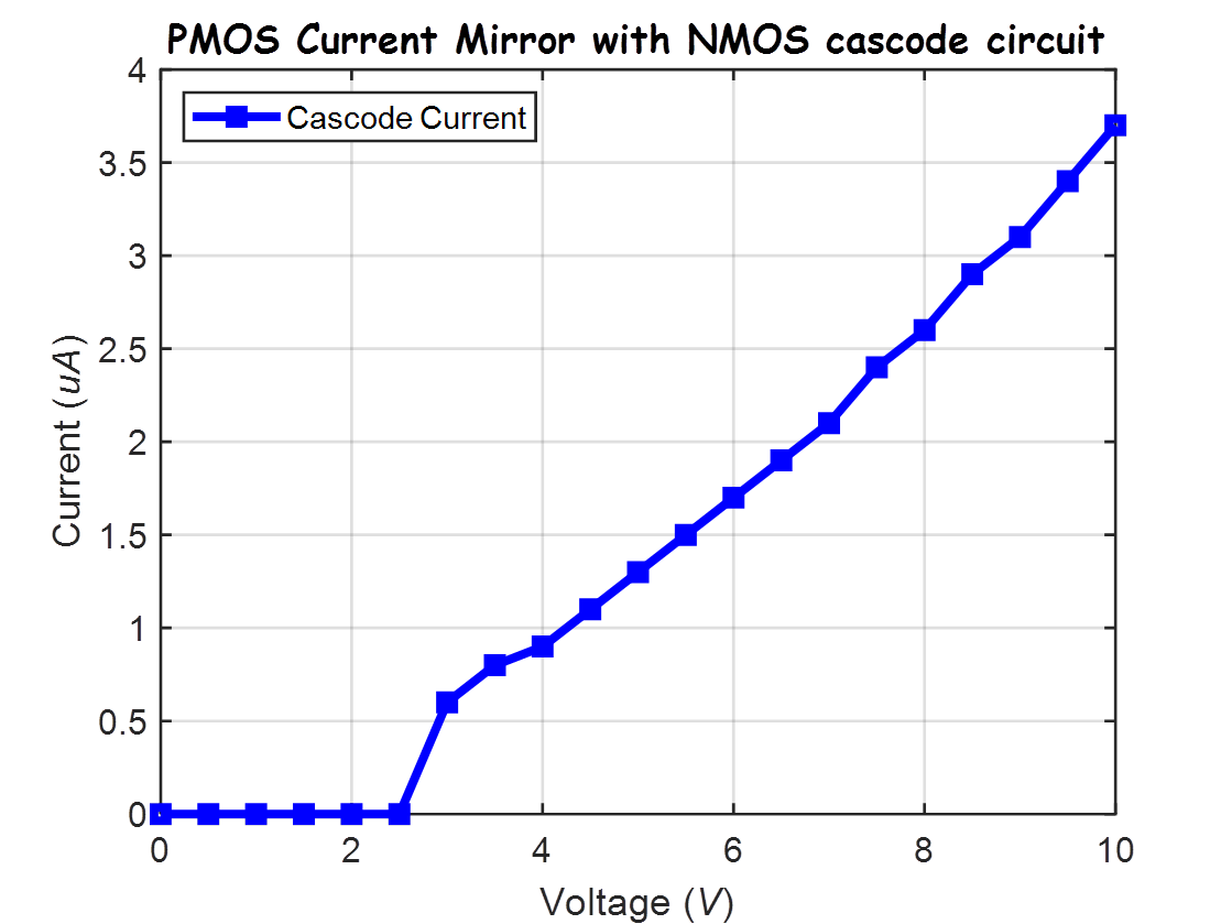
Lastly, the
student used the PMOS current mirror to drive a cascade NMOS circuit and measured
the current.
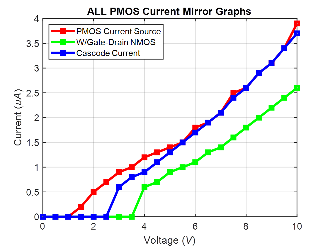
The student
then put the plots all on one graph to be able to compare the differences in
currents from the different PMOS current mirror configurations.
This lab
helps the student understand that transistor matching is important in order to make a working bias voltage reference or current
mirror.
This
concludes lab 9.
Additional Links
→ Return to listing of
lab reports
→ Daniel’s CMOS
homepage
→
Dr. Baker’s CMOS homepage