 Lab 4 – EE 420L
Authored by: Daniel Senda
Email: sendad1@unlv.nevada.edu
Spring 2019
Due: 02-27-2019
1) Introduction
This lab is intended to help students learn how to set up the
different topologies of op-amps. It also shows students how to read additional parameters
from the datasheet including gain bandwidth product and slew rate.
2) Pre-Lab Description
The pre-lab required the student to
complete the following before proceeding with lab:
- Watch the op_amps_II video and read
review.
- Simulate the circuits given in the
op_amps_II.zip file and understand operation.
- Read the entire lab write-up before going to class.
3) Description of Lab
Procedures
This lab utilized the LM324 operational amplifier (op-amp).
The datasheet can be found here.
For the
first part of the lab, the student was instructed to
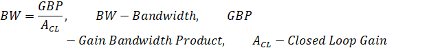
estimate the bandwidths for non-inverting op-amps topologies having gains of 1,
5, and 10 using the datasheet. The following image is from the datasheet showing
the value of the gain bandwidth product, which is used to calculate the
bandwidth with respect to gain.
![]()
In addition,
the student had to experimentally verify the
calculated bandwidths assuming a common-mode voltage of 2.5 V.
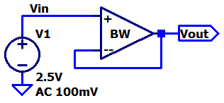
Gain of 1 (Non-Inverting Topology):
Calculated bandwidth with unity gain (gain of one) using the non-inverting topology.
![]()
The student built the
following circuit on the breadboard to get experimental data to verify the calculated
value.
Non-inverting topology (Gain 1)
circuit:
After
powering the circuit and adjusting the parameters of the lab equipment, the following
waveform was created.
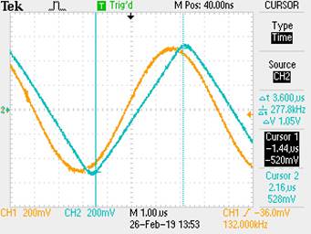
Oscilloscope waveform results:
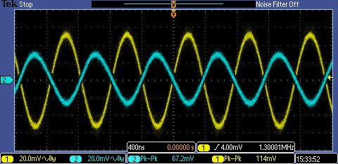
The yellow/orange signal is Vin and the blue input is Vout
(this signal color coding is kept constant throughout this entire lab). As can
be noted, the magnitude of the output is about 0.707 the input voltage at the
frequency of 1.3MHz. This is the 3dB point where the output signal starts to
roll off. These experimental results support the calculated value.
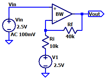
Gain of 5 (Non-Inverting Topology):
Calculated bandwidth with gain of 5 using the non-inverting topology.
![]()
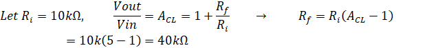
The student made the following
calculations figure out which resistor values to use when building the circuit that
would have a gain of 5.
Non-inverting topology (Gain 5)
circuit:
Oscilloscope waveform results:
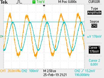
The results from the oscilloscope show the 3dB point where Vout starts to roll-off is at 190kHz. The experimental data
is different than the calculated value, and this
difference can be traced back to the variation of electrical components used to
build the circuit. Also, the op-amp is not ideal.
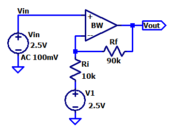
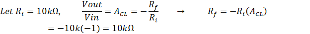
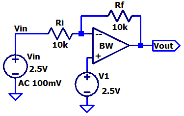
Gain of 10 (Non-Inverting Topology):
Calculated bandwidth with gain of 10 using the non-inverting topology:
![]()
The student made the following
calculations figure out which resistor values to use when building the circuit that
would have a gain of 10.
Non-inverting topology (Gain 10)
circuit:
Oscilloscope waveform results:
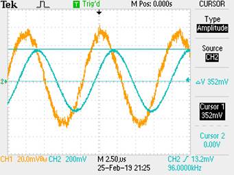
The results from the oscilloscope show the 3dB point where Vout starts to roll-off is at 96kHz. The experimental data
is different than the calculated value. Also, the op-amp is not ideal and the difference here can
also be traced back to the variation of electrical components used to build the
circuit.
For the
second part of the lab, the student was instructed to
estimate the bandwidths for inverting op-amps topologies having gains of -1, -5,
and -10 using the datasheet. The student also had to
experimentally verify the calculated bandwidths assuming a common-mode
voltage of 2.5 V.
Gain of -1 (Inverting Topology):
Calculated bandwidth with a gain of negative one using the inverting topology.
![]()
The student built the
following circuit on the breadboard to get experimental data to verify the calculated
value.
Inverting topology (Gain -1) circuit:
Oscilloscope waveform results:
As can be noted, the magnitude of the output is about 0.707 the input voltage
at the frequency of 800kHz. This is the 3dB point. These experimental results are
off from the calculated results. The could be due to the fact
that the circuit is not ideal.
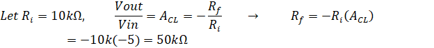
Gain of -5 (Inverting Topology):
Calculated bandwidth with a gain of negative five using the inverting topology.
![]()
The student built the
following circuit on the breadboard to get experimental data to verify the calculated
value.
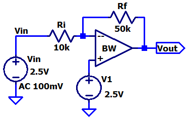
Inverting topology (Gain -5) circuit:
Oscilloscope waveform results:
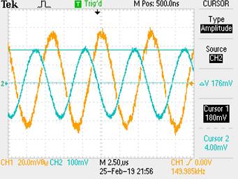
The results from the oscilloscope show the 3dB point where Vout
starts to roll-off is at 150kHz. The experimental data is different than the calculated value. This difference could be because
of the variation of electrical components used to build the circuit.
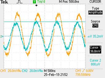
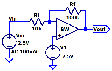
Gain of -10 (Inverting Topology):
Calculated bandwidth with a gain of negative ten using the inverting topology.
![]()
The student built the
following circuit on the breadboard to get experimental data to verify the calculated
value.
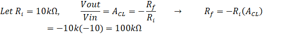
Inverting topology (Gain -10)
circuit:
Oscilloscope waveform results:
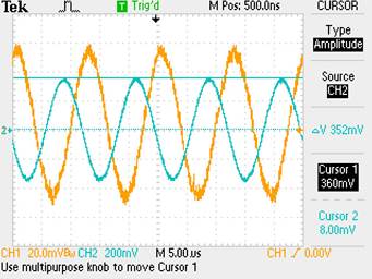
The results from the oscilloscope show the 3dB point where Vout
starts to roll-off is at 82kHz. The experimental data is different than the calculated value. The op-amp is not ideal which
could cause the difference.
The last
part of the lab had the student create two circuits to measure the slew rate of
the LM324. One of them had to make use of a pulse waveform while the other had
to make use of a sine wave.
Slew rate info from datasheet:
![]()
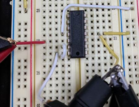
Picture of the circuit:
The same circuit was used for both versions, the only difference was the input
voltages. This first input voltage is a pulse wave and the other is a sine
wave.
Slew rate with pulse wave input:
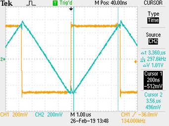
Slew rate with sine
wave input:
The slew rate that was measured experimentally was close to what the datasheet
has.
This concludes lab 3. (Lab was backed-up on an external
drive)
Additional Links
→ Return to listing of
lab reports
→ Daniel’s CMOS
homepage
→
Dr. Baker’s CMOS homepage