 Lab 2 – EE 420L
Authored by: Daniel Senda
Email: sendad1@unlv.nevada.edu
Spring 2019
Due: 02-06-2019
1) Introduction
This lab is intended to help students learn how to properly test circuitry
using a correctly compensated oscilloscope probe and the importance on setting
equipment up properly.
2) Pre-Lab Description
The pre-lab
required the student to complete the following before proceeding with lab:
- Watch scope probe video and read review.
- Change parameters of scope probe
simulation to get a good understanding of a 10:1 probe.
- Understand operation and analysis of
simple RC circuits.
- Understand and know bode plots.
- Read the entire lab write-up before
going to class.
3) Description of Lab
Procedures
In order to
get accurate readings from an oscilloscope, the user is required to use of the
appropriate probes that are compensated correctly. If
a probe is not compensated correctly, it will give the
user distorted results. The first part of the lab procedures had the student
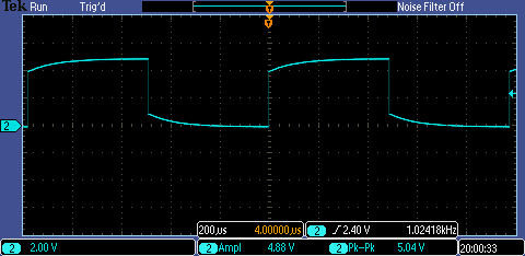
undercompensate, overcompensate, and correctly compensate a 10:1 probe.
Undercompensated probe:
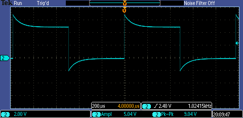
Overcompensated probe:
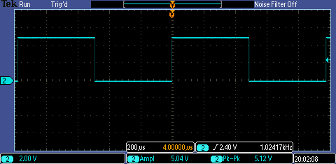
Correctly compensated probe:
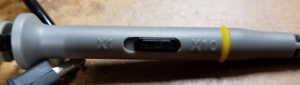
The
oscilloscope was used was set to read a 10:1 probe. If the oscilloscope were to
be on the 1:1 probe setting, it would still read the signal but the scale of
the reading would be off by a factor of 10. Having the correct setting is
important to get correct readings. (Picture
of probe):
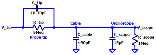
The
following schematic is of a 10:1 oscilloscope probe. It shows the 9MΩ resistor and 10-20pF capacitor (which can
typically be adjusted to properly compensate the probe) that are found
in the tip of the probe. The cable of the probe also has a capacitance that is
about 90pF per meter. The other end of the probe connects to the oscilloscope,
which usually has a 1MEG resistance and a 15pF capacitance.
LTspice schematic of compensated probe
circuit:
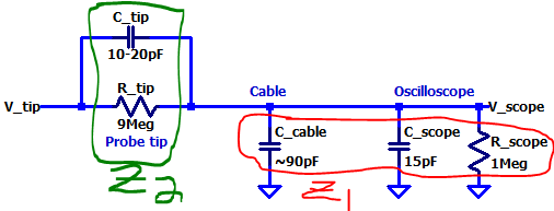
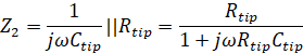
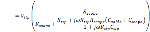
The following
calculations show how the Vscope voltage
is ten times smaller than Vtip. Also, note
that the probe tip capacitance should be adjusted to
45pF (in this case) to get a precise 10:1 probe reading.
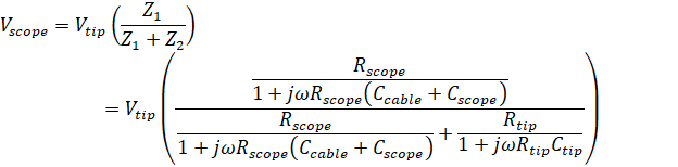
To show that
the voltage at Vscope is 1/10th
of the voltage at Vtip, the following
assumptions were made:
|
Variable |
Vtip |
Ctip |
Rtip |
Ccable |
Cscope |
Rscope |
Vscope |
|
Value |
1V |
45pF |
9MΩ |
90pF |
15pF |
1MΩ |
Will solve |


![]()
![]()
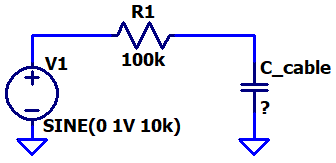
The next lab
procedure was to create an experiment circuit to determine the capacitance of the a cable. A simple RC circuit was made,
with a resistor value of 100kΩ. The piece of cable was put into the circuit as a capacitor. The next step was
to sweep the frequency of the input source until the student was able to see
the charge and discharge time of the capacitor formed by the cable. The RC time
constant was measured, and then the capacitance was
found through hand calculations. The student verified the calculated
capacitance with a capacitance meter.
LTspice schematic of circuit:
Time constant (τ =
8.4µs) measured through the oscilloscope:
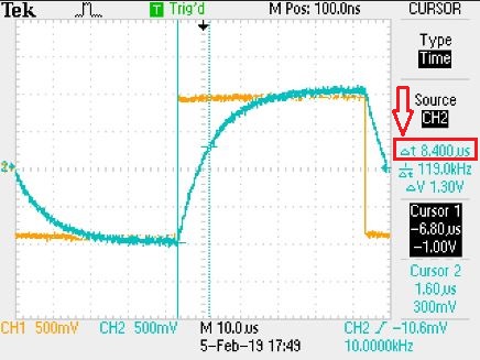
Note, the frequency that allowed to capture charging and discharging of the
capacitor was 10kHz.
From the τ measurement, the following calculations
were made to solve for capacitance:
![]()
![]()
Capacitance of cable measured through
LCR meter:
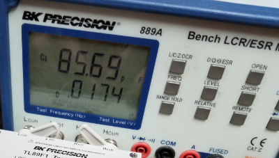
As can be seen, the calculated capacitance was really close the measured
capacitance value of the cable.
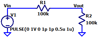
Following
the procedures, the student’s next task was to build a voltage divider using
two 100k resistors. The input of the divider was required to be a 1MHz pulse
going from 0 to 1V. The student had to measure the
output two ways, using a regular cable and using a correctly compensated probe.
LTspice circuit of voltage divider:
Measurements
from the oscilloscope of Vout (output) of the voltage
divider are shown below:
Uncompensated cable: Compensated probe:
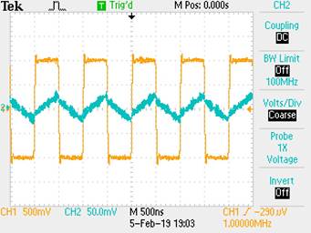
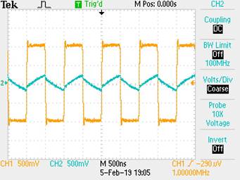
Analyzing the pictures, the uncompensated cable has a distorted signal reading
while the compensated probe has a clean signal reading. In conclusion, anyone
who uses an oscilloscope should use a compensated probe when measuring to get
more precise signal readings (especially at higher frequencies).
Lastly, the
student was required to discuss the proper implementation of a test point on a
printed circuit board so that a known length of cable could
be connected directly to the board and not load the circuitry on the
board.
- In order to test points on a board with an uncompensated cable without
loading the circuitry, the student must take design
precautions into consideration. First, the student should implement a
resistive and capacitive load (like is seen at the tip of a compensated probe)
on the circuit board itself. The student can also incorporate a variable
capacitor instead of a fixed capacitor so the capacitance can
be adjusted for different lengths of cable. This test-point design would
no longer require a compensated probe because the compensation would be already taken care of on the circuit board.
This
concludes lab 2. (Lab was backed-up on an external drive)
Additional Links
→ Return to listing of
lab reports
→ Daniel’s CMOS
homepage
→
Dr. Baker’s CMOS homepage