Lab 2 - ECE 421L
Clayton Frister,
FristerC@unlv.nevada.edu
January 30, 2017
Lab 2: Operation of a Compensated Scope Probe
Perform, and document in your html lab report, the following:
- Show scope waveforms of a 10:1 probe undercompensated, overcompensated, and compensated correctly.
- Comment
on where the type of scope probe (i.e., 1:1, 10:1, 100:1, etc.) is set
on your scope (some scopes detect the type of probe used automatically).
- Draft
the schematic of a 10:1 scope probe showing: the 9 MEG resistor, 1 MEG
scope input resistance, capacitance of the cable, scope input
capacitance, and capacitance in the probe tip.
- Using circuit analysis, and reasonable/correct values for the capacitances, show using circuit analysis and alegbra (no approximations), that the voltage on the input of the scope is 0.1 the voltage on the probe tip.
- Devise
an experiment, using a scope, pulse generator, and a resistor, to
measure the capacitance of a length of cable. Compare your measurement
results to the value you obtain with a capacitance meter. Make sure you
show your hand calculations.
- Build
a voltage divider using two 100k resistors. Apply a 0 to 1 V pulse at 1
MHz to the divider's input. Measure, and show in your report, the
output of the divider when probing with a cable (having a length
greater than or equal to 3 ft) and then a compensated scope probe. Discuss and explain the differences.
- Finally,
briefly discuss how you would implement a test point on a printed
circuit board so that a known length of cable could be connected
directly to the board and not load the circuitry on the board.
1. Show scope waveforms of a 10:1 probe undercompensated, overcompensated, and compensated correctly.


Undercompensated
Probe
Overcompensated Probe
Correctly
Compensated Probe
2.Comment
on where the type of scope probe (i.e., 1:1, 10:1, 100:1, etc.) is set
on your scope (some scopes detect the type of probe used automatically).
To
set the scope probe to the appropriate ratio you need to press the
channel button for the channel that you are using (they are color
coded). Then a new menu pops up at the bottom to which you should
select probe setup, and then another menu pops up on the right and you
can select 1x or 10x probe from the menu on the right. See picture
below.


Scope Probe Selection
10x Scope Probe
Experiment 3:
Draft the schematic of a 10:1 scope probe showing: the 9 MEG resistor,
1 MEG scope input resistance, capacitance of the cable, scope input
capacitance, and capacitance in the probe tip.

10:1 Probe Schematic
The
schematic above is the schematic shown in Dr. Bakers video. Below is a
screen shot of the input wave form being attenuated to one tenth of the
input, hense the 10:1 probe ratio.

10:1 Probe Input and Output SimulationExperiment 4: Using circuit analysis, and reasonable/correct values for the capacitances, show using circuit analysis and alegbra (no approximations), that the voltage on the input of the scope is 0.1 the voltage on the probe tip.
 Experiment 5: Devise
an experiment, using a scope, pulse generator, and a resistor, to
measure the capacitance of a length of cable. Compare your measurement
results to the value you obtain with a capacitance meter. Make sure you
show your hand calculations.
Experiment 5: Devise
an experiment, using a scope, pulse generator, and a resistor, to
measure the capacitance of a length of cable. Compare your measurement
results to the value you obtain with a capacitance meter. Make sure you
show your hand calculations.
For
this experiment I measured an RC circuit using a resistor and a cable,
with the cable being the capacitor in the circuit. The resistors actual
measured value was 99.9k ohms. Using an input pulse of 1V at 100k
and measuring the output against the input I got the following result.

According
to the Cmosedu book, the delay time is from the start of the rise time
to 50% of the final amplitude of the signal (which is where I
have positioned my cursors in the photo above.) Using the 943.2nS
measured above, and the delay time equation td = 0.7RC I can calculate
the capacitance of the cable.
C = td/(0.7*R) = 943.2nS/(0.7*99.9k) = 13.3pF
First
we have to measure the capacitance of the banana cables that plug into
our multimeter. As seen in the picture they measured 0.0085nF. And then
I connected the scope probe cable to those and measured them together.
Then subtracted one from the other to get the capacitance of the cable.
(See calculations below)


Banana Cables Capacitance
Banana
Cables and Scope Cable Capacitance
CalculationsScope cable capacitance = 0.0244nF - 0.0085nF = 15.9pF compared to the calculated 13.3pF it's pretty close.
Experiment 6:
Build a voltage divider using two 100k resistors. Apply a 0 to 1 V
pulse at 1 MHz to the divider's input. Measure, and show in your
report, the output of the divider when probing with a cable (having a
length greater than or equal to 3 ft) and then a compensated scope probe. Discuss and explain the differences.
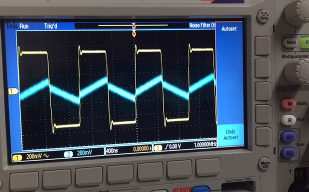

Compensated Probe
Uncompensated Probe
The
compensated probe output compared to the input shows the 10:1
attenuation that is occuring from the corrected capacitance in the
probe. The uncompensated probe on the right shows an output with large,
uncorrected, capacitance that results in an almost linear output.
Experiment 7:
Finally, briefly discuss how you would implement a test point on a
printed circuit board so that a known length of cable could be
connected directly to the board and not load the circuitry on the board.
In
order to implement a test point on a PCB so that a known length of
cable could be connected directly to the board and not load the
circuitry on the board you would want to place a resistor and a
variable capacitor in parallel to get rid of any unwanted effects from
the cable.
Return to FristerC Labs
Return to 420L Students
Return to 420L