Cadence Schematic Aesthetics Tutorial
Cadence schematic software defaults to a
black background, light blue wires, and light green components that, when
printed, are both a waste of ink, and aesthetically difficult to interpret. This
tutorial will cover how to quickly and easily change the default color and
thickness of wires and components in Cadence schematics, and how to print or
snip schematics with a white background.
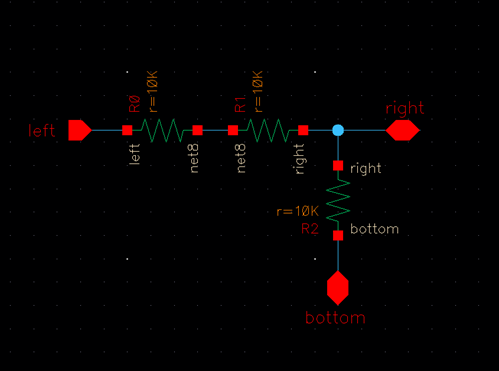
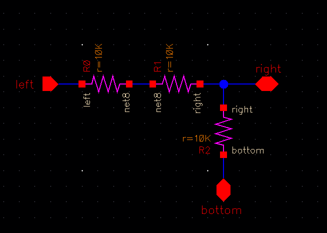
Here, we
observe a simple voltage divider schematic, generated with Cadence schematic
software (spectre). If we needed to print this out
right now for an assignment or for any other purpose, copious amounts of black
ink would be wasted on the background, and the lighter colors of the components
and wires would not show up on a black or a white background very well.
Thankfully, there is a solution.
We will first discuss how to change the color and
thickness of the components and wires.
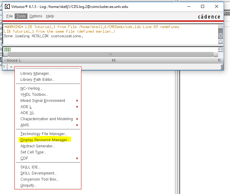
Bring up the
CIW (Command Interpreter Window) and click on Tools » Display Resource Manager
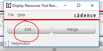
A small window
will pop up called the Display Resources Tool Box window. Click Edit.
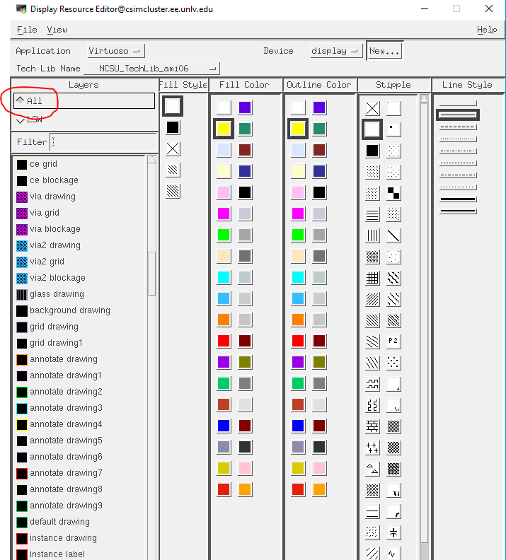
The Display
Resource Editor window will pop up, shown below. Be sure to switch the Layers
selector to All.
We can now navigate
through the various items that Cadence has default colors for. We are
specifically interested in “device drawing1” (for editing the color of
schematic components), “wire drawing”, and “wire label”. The process for
changing the color and thickness for each individual item is always the same,
so we will just go through the process for the color and thickness of the wire.
The first thing we will do is select “wire drawing” in the scroll menu on the
left.
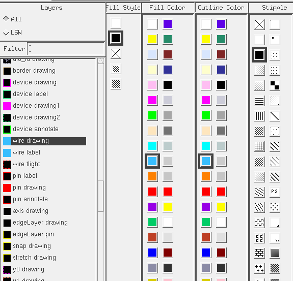
We can see
that the defaults for the fill color and outline color of the wire are light
blue. We can also see that the default thickness is not very thick at all.
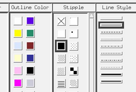
We can now
select a new wire color and thickness. In the tutorial, we will select dark
blue, and medium line thickness (mline). Be sure to hit Apply.
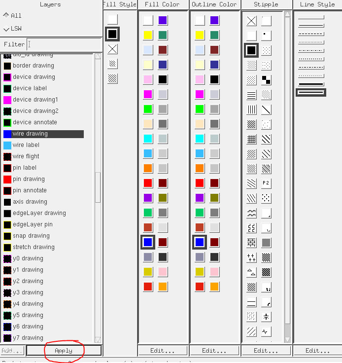
Once you have
hit Apply, go to File » Save.
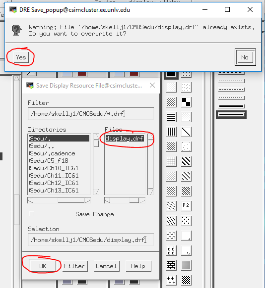
When the Save
Display Resource File window pops up, under Files, click display.drf.
Click OK.
A pop up will
ask you if you would like to overwrite the display file. Click Yes.
Be sure to
close and reopen whatever schematic you were working on in
order to activate the change in color and thickness.
Repeat this
process for “wire label” and “device drawing1” to thicken and change colors of
components and wire names.
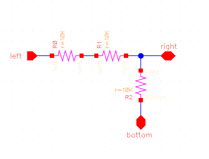
The components
have been thickened and changed to a pink color.
The new
schematic will look like the following.
Now that the schematic
is darker and thicker, we can be sure it will show up better on a white
background.
This part of the tutorial will cover how to pull
up the schematic with a white background for printing purposes.
We first need
to use the Zoom command (Z) to crop the schematic view to exactly what we want our
snip to look like.
In the photo
above, this is already done.
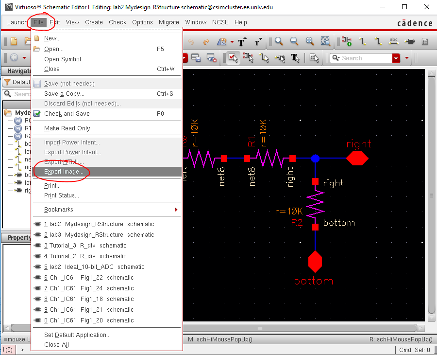
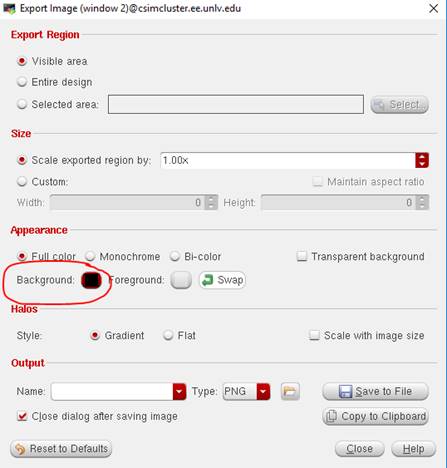
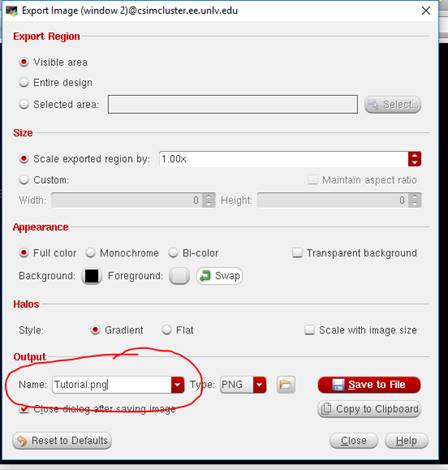
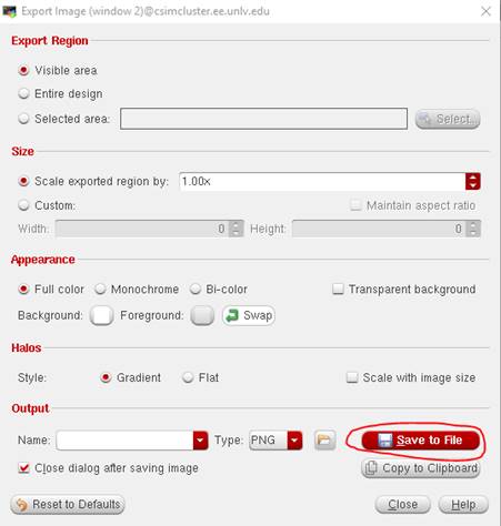
Next, go to
File » Export Image, and the Export Image window will pop up, seen below.
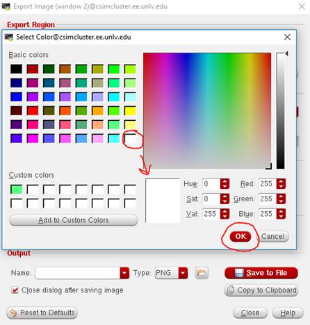
Select
Background and change the background color to white. Click OK, circled below.
Next, we need
to name the file, seen below (you do not need to add .png
to the file name, the software will do that on its own as
long as you set the file type to PNG). After naming the file, select
Save to File.
At this point,
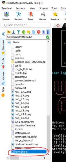
we are pretty much done. We need to simply navigate back to the MobaXTerm to find the file.
Open up the MobaXTerm and navigate
to the CMOSedu directory (you may have to hit the
green refresh button in order for the file to pop up in the CMOSedu
directory). Down below your libraries you will find your .png
file, which is now an image of the schematic with a white background, that can
be snipped, or copied and pasted into a file to be printed.
This is the
end of the tutorial. Hopefully it will save you lots of ink and frustration!