Connecting
to Vias and Ground Plane in Eagle
Overview: Guide
will explain how to create and connect to vias and ground planes using
Eagle
Additional
Help: Adding Vias; Ground Plane
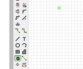
Vias
are placed on the PCB to provide a stronger ground connection between
the top and bottom ground layers and to prevent intersecting
connections. To place a via, use the via tool. Unless needed as
otherwise, the default values are good
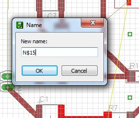
To connect the via to a device, rename the via identical to the desired
airwire. Be sure to use the Name tool
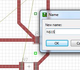
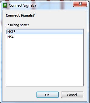
After naming the via, another window will pop up asking to connect the
signals. Click OK.
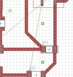
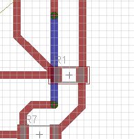
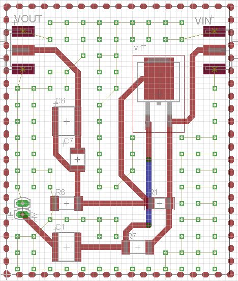
By
using this method, you can create wires on the bottom layer that will
connect to wires on the top layer and prevent wires from crossing. By
default, red wires are on the top layer and blue wires are on the
bottom layer
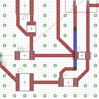
As mentiond, vias will improve the ground connection. Thus, vias are
placed evenly around the board in the empty spots
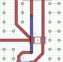
To
connect the vias to ground, the vias must be renamed to GND in a
similar method to before. Air wires will show the connection to ground
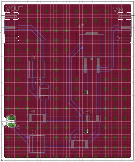
To
create a ground plane, select the polygon tool. Be sure that the top
layer is selected and that the polygon will cover the entire board. A
dotted line should appear around the board outline. Rename the polygon
GND
Repeat
the step, but create the polygon on the bottom layer. After renaming
the bottom layer polygon to GND, select Ratsnest and the board is
complete. The GND airwires should no longer show.
Updated:
06/30/2014
Return to Main Page
Return
to Students Home