Lab 1 - ECE 421L
Created and edited by Michael Parker
Email : parkem3@unlv.nevada.edu
Last updated : August 31 2021
Pre-Lab
- Prior to the first day of lab, but not to exceed one week before the
lab, request a CMOSedu account from Dr. Baker.
- Review material given for editing webpages. (material found here)
Lab Overview
The purpose of this lab is to familiarize yourself with setting up
Cadence, creating a new library, drafting a circuit, and simulating
that circuit.
Lab Procedures
As we began the lab we were to download the NCSU Cadence Design Kit
(CDK) and extract it to our home folder. With this accomplished, we
were to edit our .bashrc file and the cds.lib file with the following respectively.
export SPECTRE_DEFAULTS=-E
export CDS_Netlisting_Mode=Analog
export CDS_LOAD_ENV=CWDElseHom
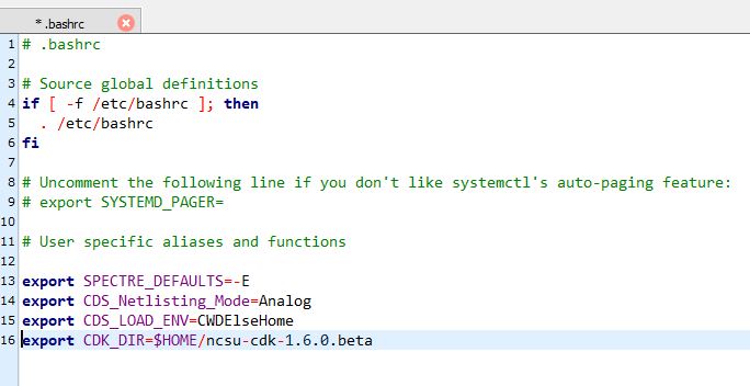
fig.1
DEFINE analogLib /usr/cadence/IC615/tools.lnx86/dfII/etc/cdslib/artist/analogLib
DEFINE functional /usr/cadence/IC615/tools.lnx86/dfII/etc/cdslib/artist/functional
DEFINE sbaLib /usr/cadence/IC615/tools.lnx86/dfII/etc/cdslib/artist/sbaLib
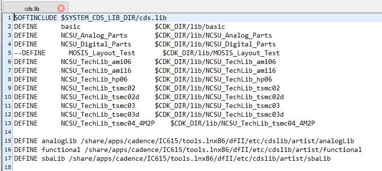
fig. 2
One final piece of setup was needed for us to be up and running. There
is an error with the rule files in the ami06 tech library and we needed
to fix that by replacing the old files with new downloaded files.

fig. 3
In order to accomplish this we navigated to the rule files in the ami06
tech library found in our home directory under $HOME/ncsu-cdk-1.6.0.beta/lib/NCSU_TechLib_ami06.Once inside that directory we deleted divaDRC.rul, divaEXT.rul, and divaLVS.rul and replaced them with the new files from here. (fig. 3)
Now that we had set up everything that we needed to get started with
cadence we could open up our terminal window navagate to the CMOSedu
directory and typed virtuoso & in order to launch Cadence.
If Cadence launches correctly you should be greeted with the image
below (fig. 4). Our next step was to create a new library for our
schematic to be created in, and we did this by selecting file > new
> libreary at the top of the libreary manager
window. This will popped up a new window (fig. 5) where we named our
library, attached the AMI06 tech library to it, and selected OK. This
can be checked by navigating to your cds.lib and seeing the image below
(fig. 6) defining that library.


fig. 4
fig. 5
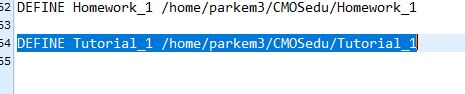
fig. 6
Now that we have our library we are going to start creating our
schematic. With our created library selected in the manager window, we
selected File > New > Cell View and the next window (fig. 7)
popped up allowing us to name the cell etc.

fig. 7
With the cell window open we could start drafting our circuit. First
two resistors were needed one horizontal and one verticle. This was
achieved by hitting the I key in order to pull up the component window,
selecting R L C from the analog menu and selecting res for resistor.
This popped out a new window that allowed us to input the resistance of
each resistor. Once the parameters were set all that was needed was a
simple left click to set the resistor or a right click to
rotate it before setting it (fig. 8).
Next, we added a ground in the same way, added a 1V voltage source
(fig. 9), added wires connecting everything, and finally namec the
input voltage node (in) and output voltage node (out) (fig. 10).


fig. 8
fig. 9

fig.
10
After all of the previous design steps were completed we had a schematic that looked like this (fig. 11).

fig. 11
Next was the simulation of the circuit. First I saved and checked the
circuit for any errors (fig. 12). With that complete I opened the ADE
L, but there was anerror and it launched ADE XL instead (fig. 13).

fig. 12

fig. 13
The first thing I needed to do was to select the type of simulation
that i wanted to run. I selected transient and one second (fig. 14).
Then i selected the nodes to be plotted and saved the state (fig. 15)
in order to save time when running the simulation in the future. I then ran the simulation which outputted the final results (fig. 16).


fig. 14
fig. 15

fig.16
Periodic Backup
During the course of a lab and writing my lab report I want to be
able to protect my work from possible loss or error. I backed
everything up by saving all of my files to a single folder, zipping
that folder (fig. 17) and emailing it to myself periodically, about
once every 30 minutes (fig. 18).


fig.
17
fig.18