Lab 5 - ECE 421L
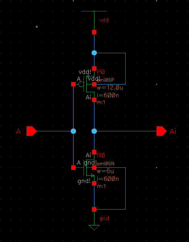
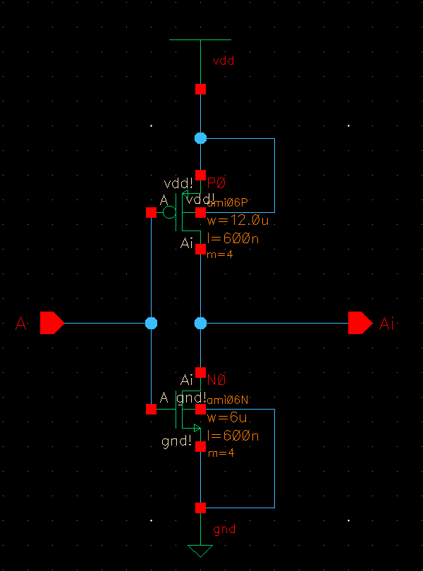
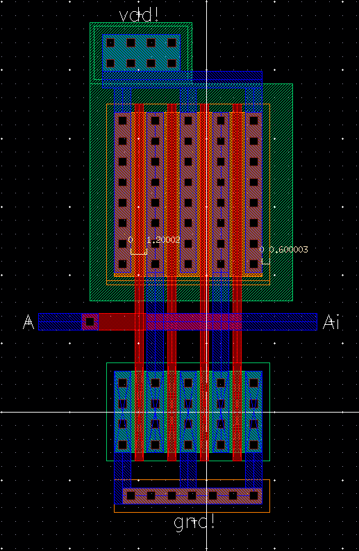
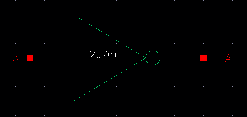
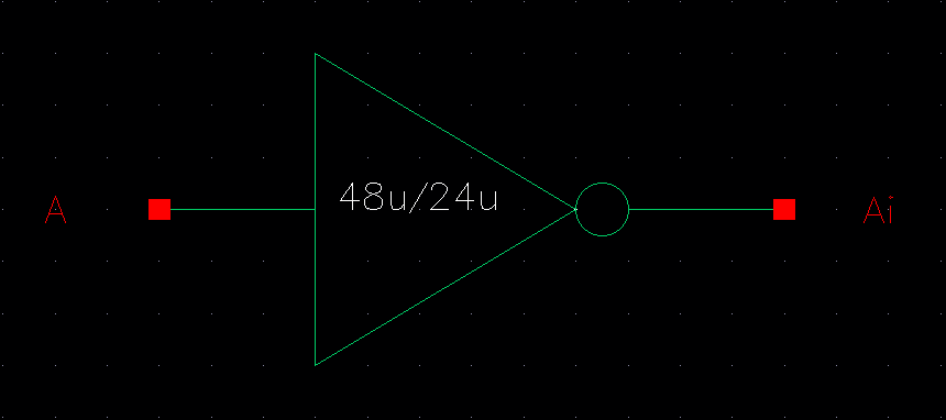
| 12u/6u | 48u/24u |
|
|
|
|
|
|
|
|
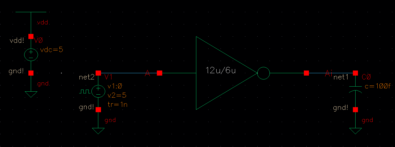
Simulations
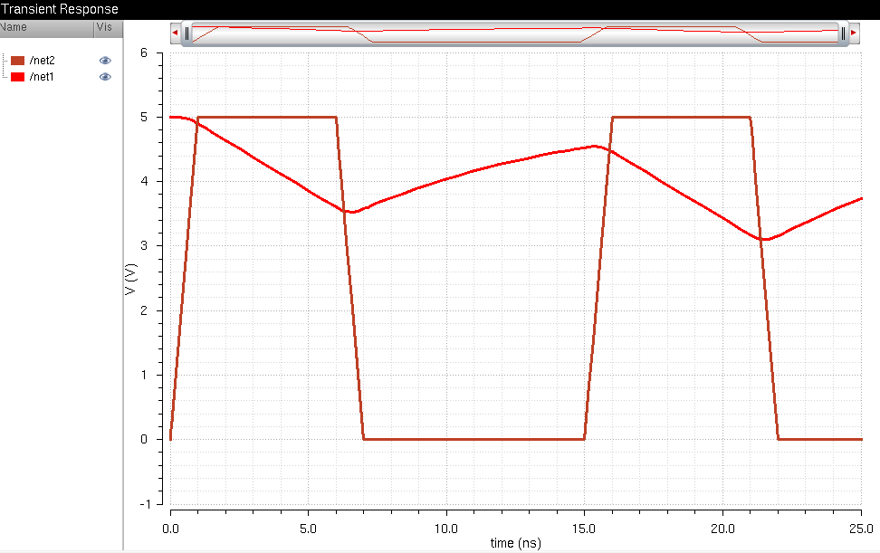
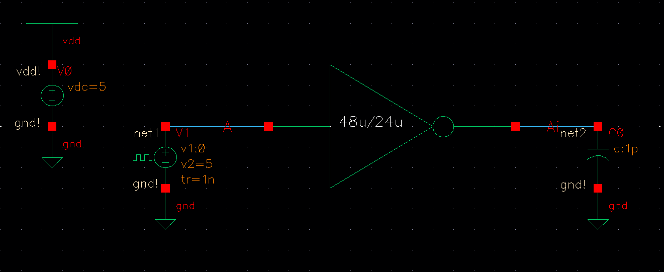
The
following schematic will be simulated. The capacitance will increase
slightly with each increment simulation and the results are shown below
the schematic.
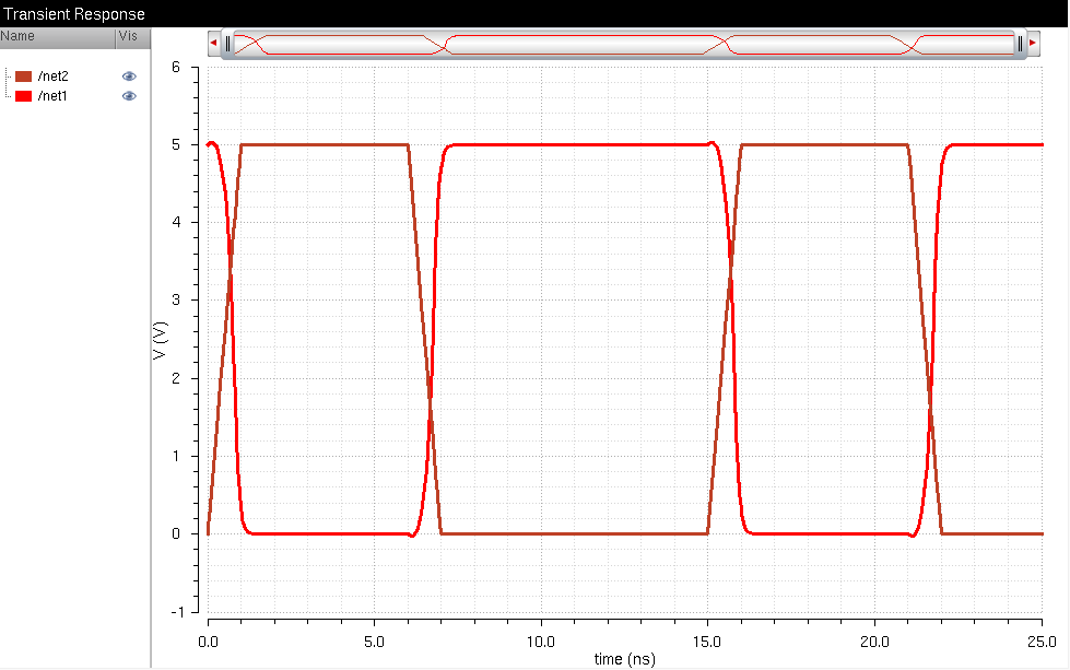
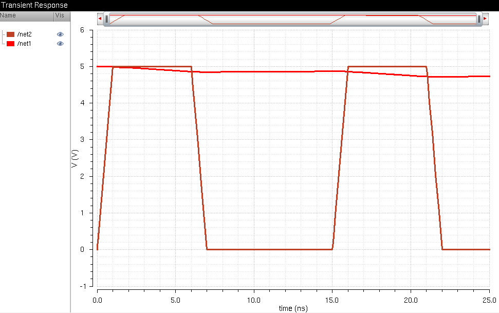
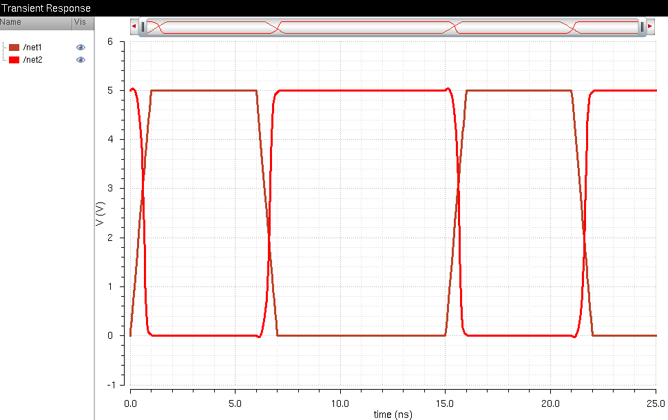
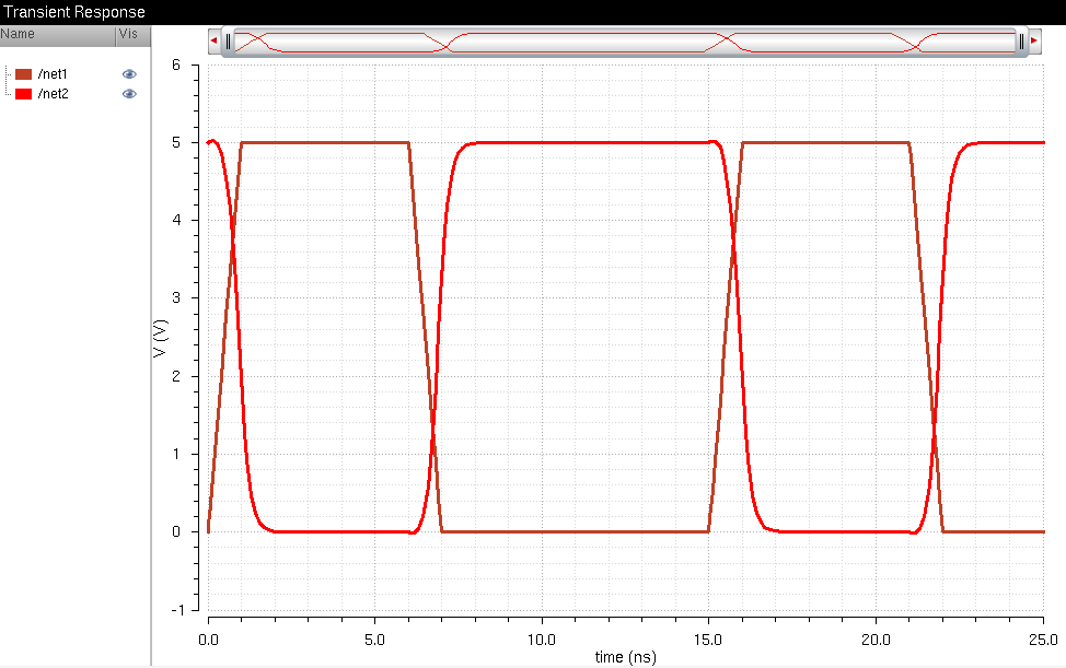
| 100 fF | 1 pF |
 |
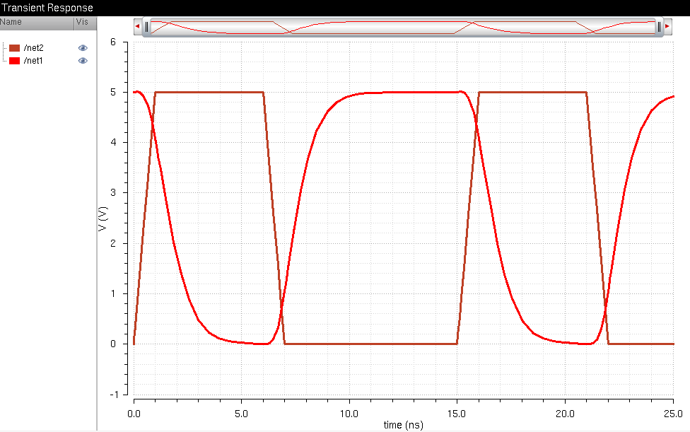 |
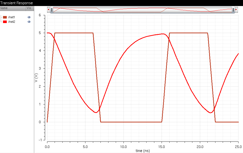
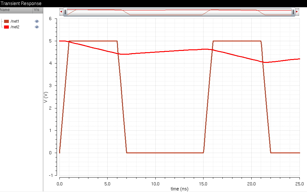
| 10 pF | 100 pF |
 |
 |
Animation showing progressive increase in capacitance:
The following schematic will be simulated. The capacitance will increase slightly with each increment simulation and the results are shown below the schematic.
| 100 fF | 1 pF |
 |
 |
| 10 pF | 100 pF |
 |
 |
Animation showing progressive increase in capacitance: