Finish Tutorial 4.

This ends the content of the Prelab.
Create layout and symbol views for these gates showing that the cells DRC and LVS without errors
Ensure
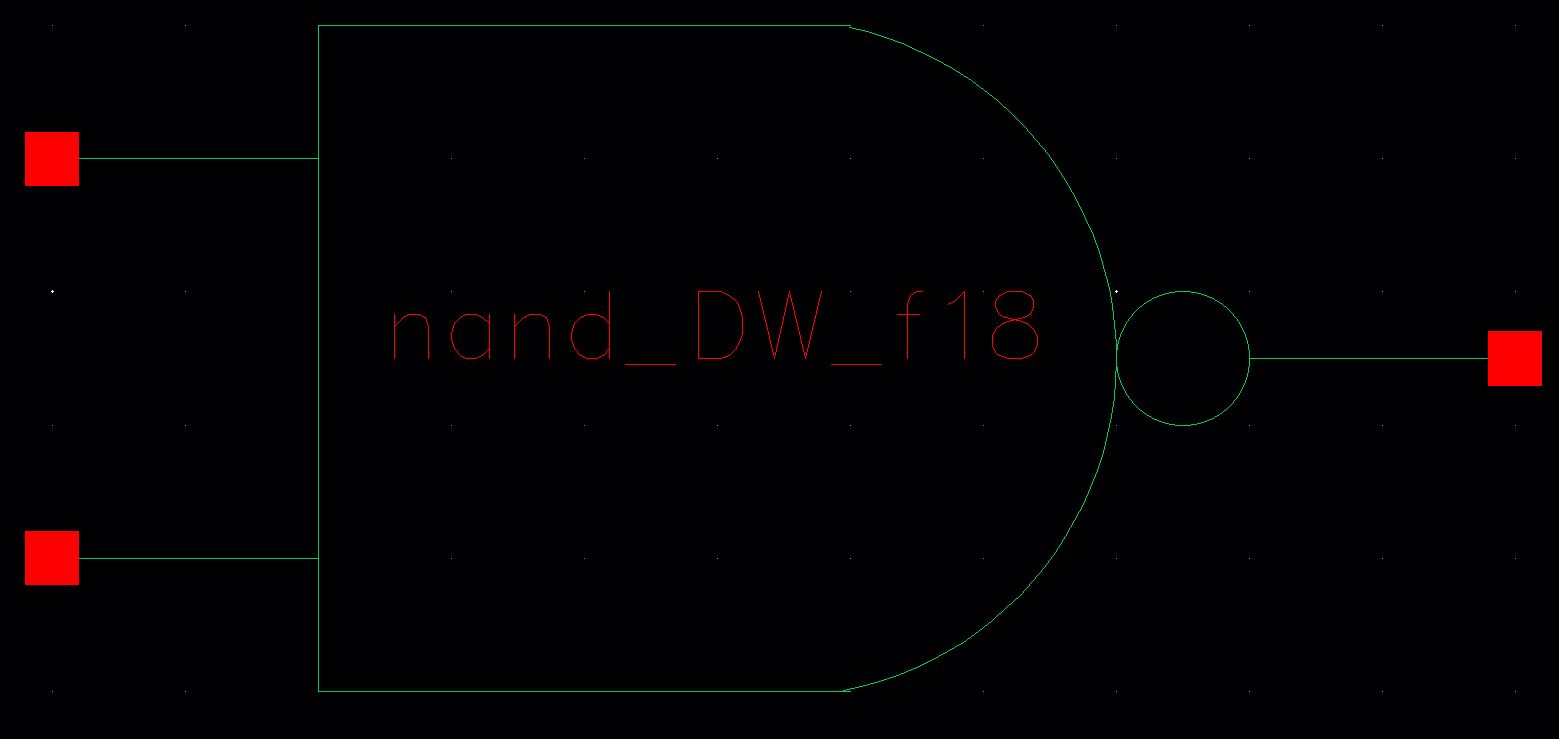
that the symbol views are the commonly used symbols (not boxes!) for
these gates with your initials in the middle of the symbol .
Ensure all layouts in this lab use standard cell frames that snap together end-to-end for routing vdd! and gnd!
Use a standard cell height taller than needed for these gates so that it can be used for more complicated layouts in the future.
Ensure gate inputs, outputs, vdd!, and gnd! are all routed on metal1.
Using Spectre simulate the logical operation of the gates for all 4 possible inputs (00, 01, 10, and 11).
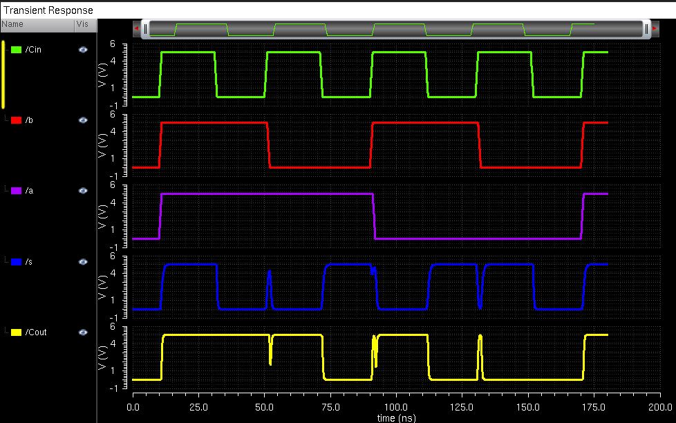
Comment on how timing of the input pulses can cause glitches in the output of a gate.
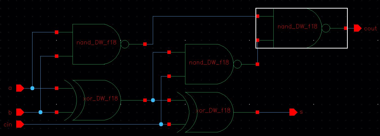
Using these gates, draft the schematic of a full adder.
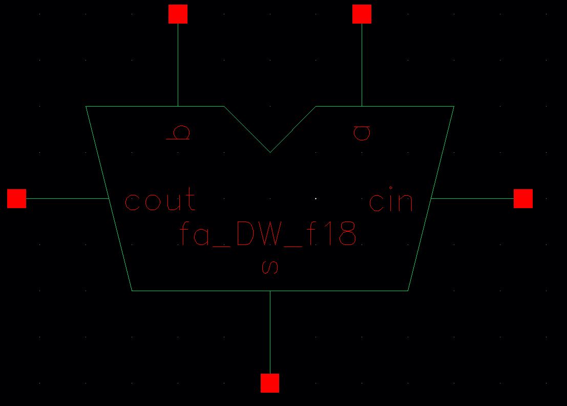
Create a symbol for this full-adder.
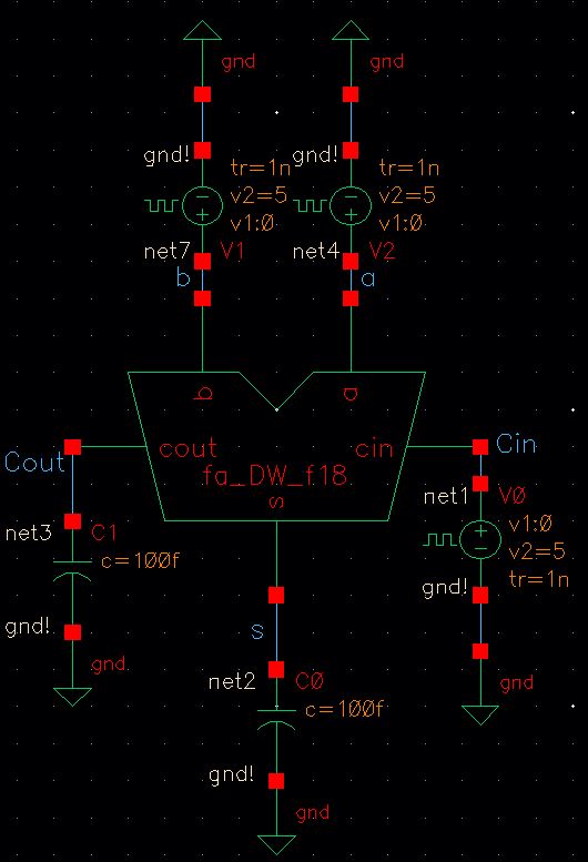
Simulate, using Spectre, the operation of the full-adder using this symbol .
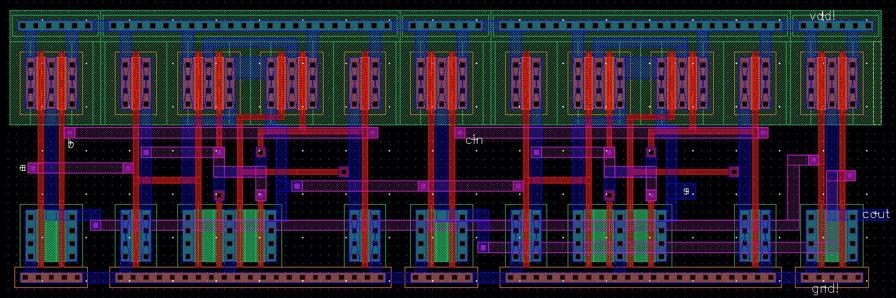
Layout the full-adder by placing the 5 gates end-to-end so that vdd! and gnd! are routed.
Full-adder inputs and outputs can be on metal2 but not metal3.
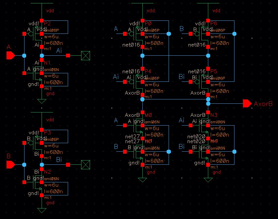
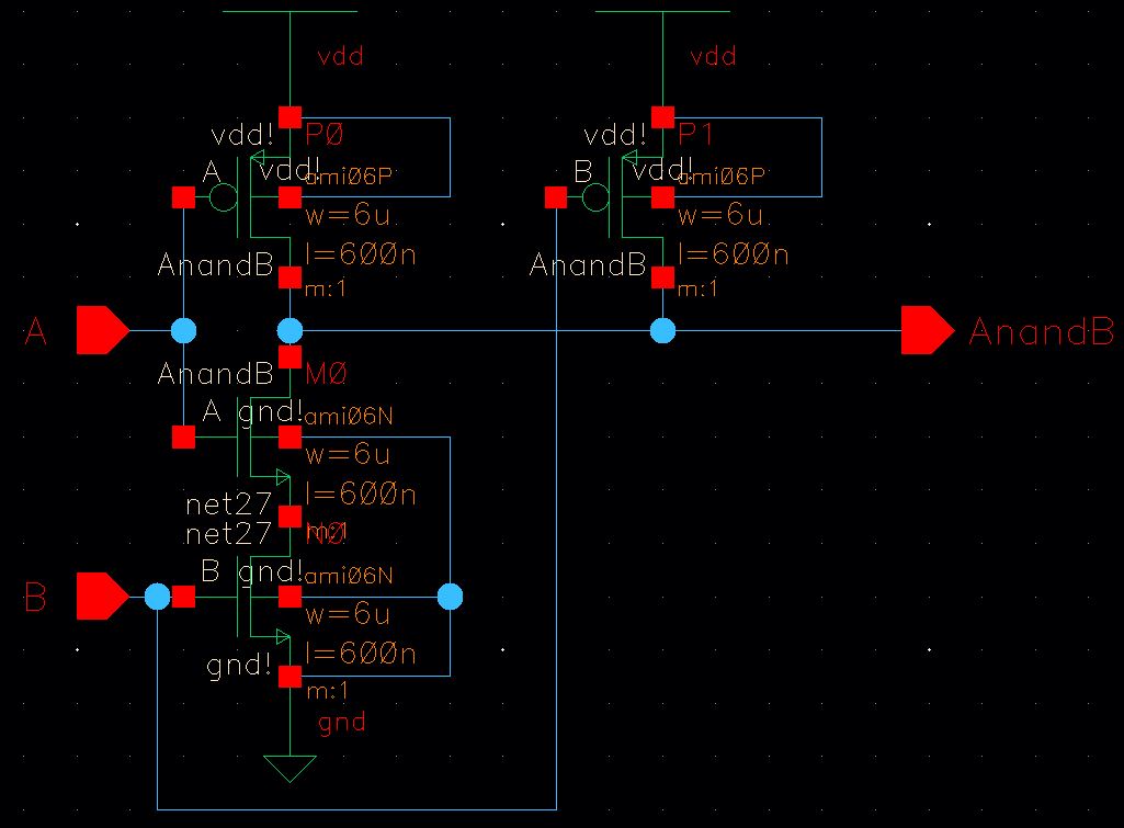
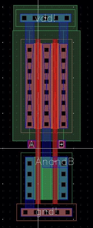
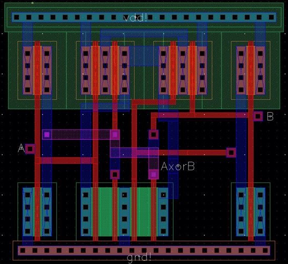
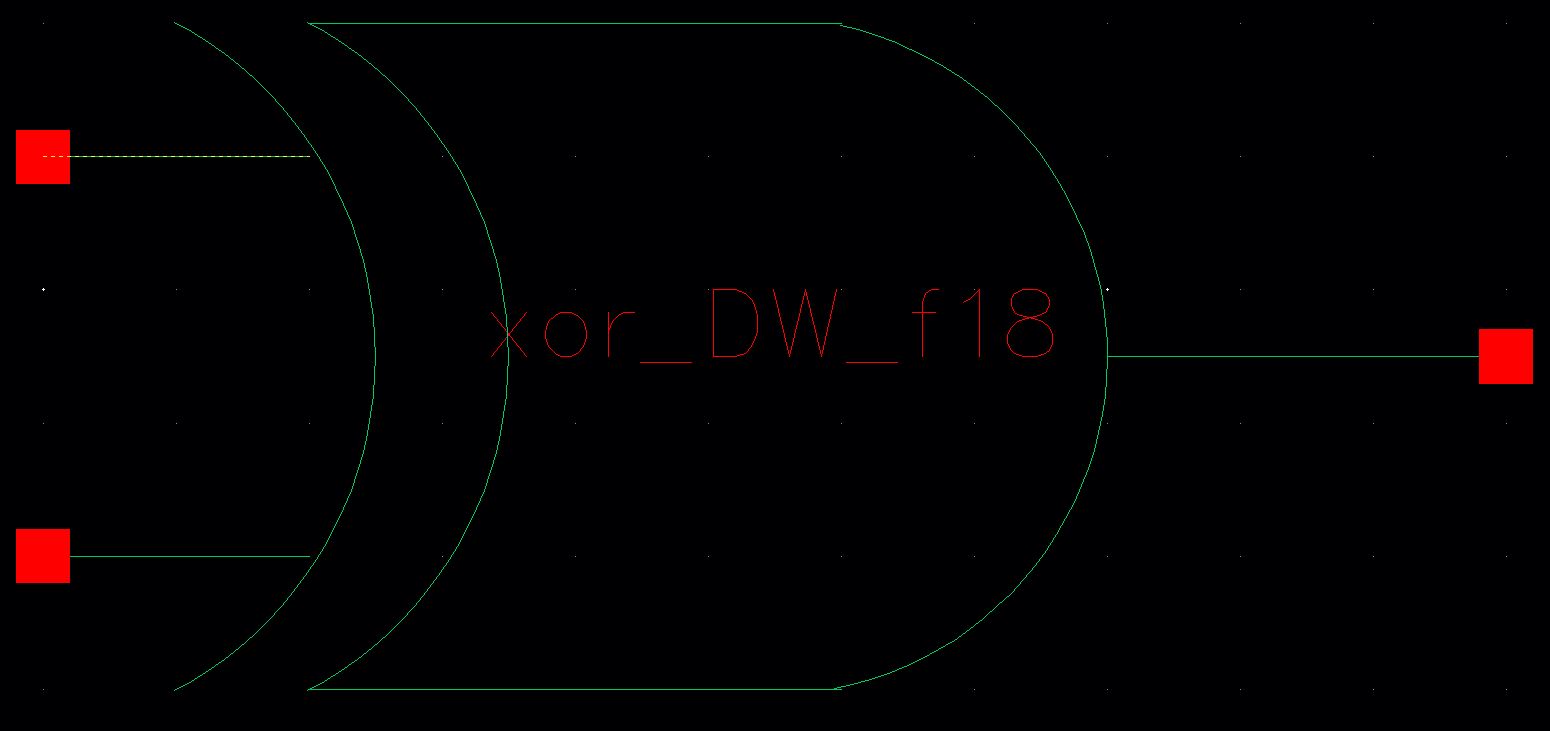
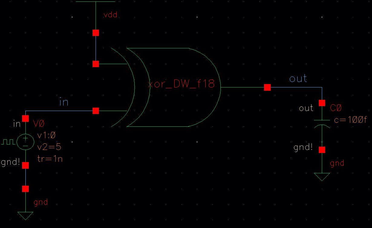
The schematic, layout, and symbol for the XOR gate are shown below:
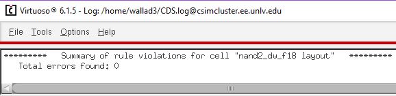
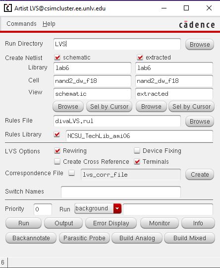
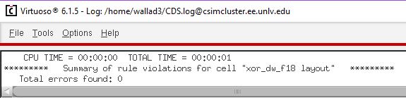
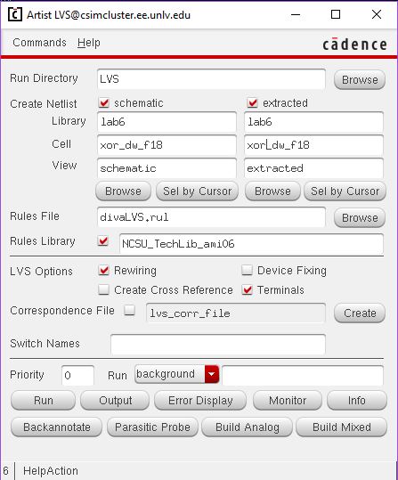
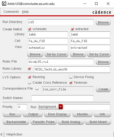
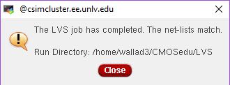
Next you should DRC, extract, and LVS the XOR gate:

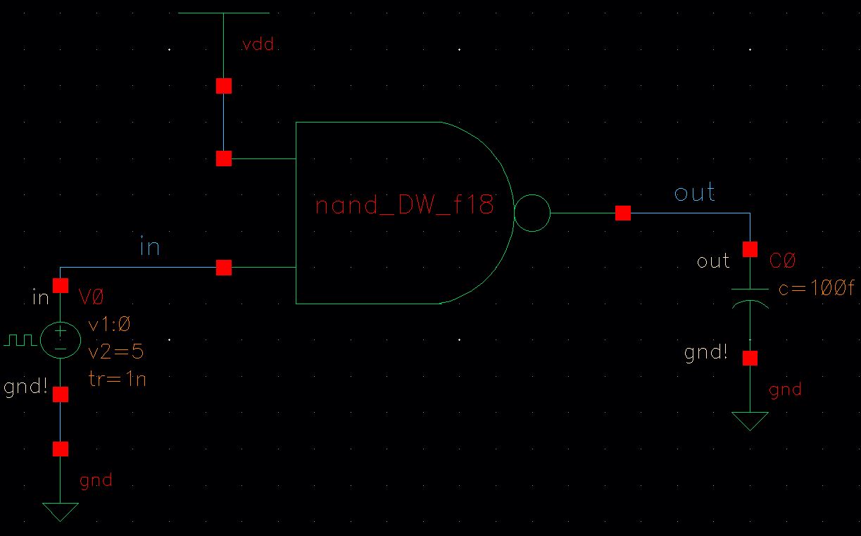
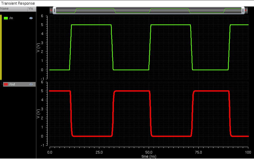
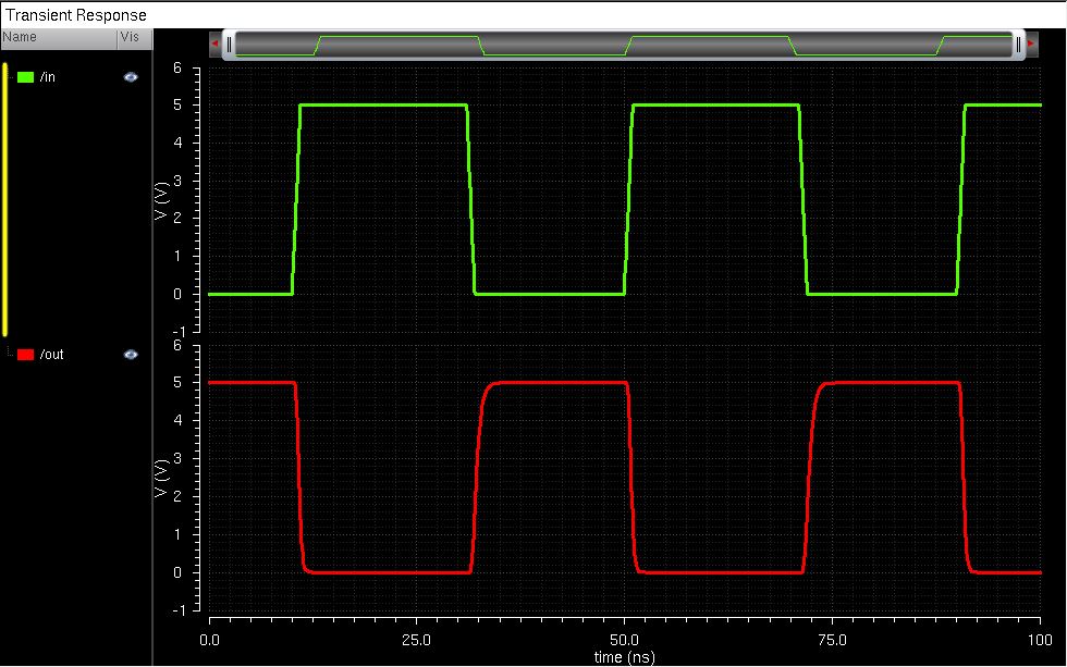
Finally, the following schematic and simulation results should be obtained:
The schematic, layout, and symbol for the Full Adder are shown below:
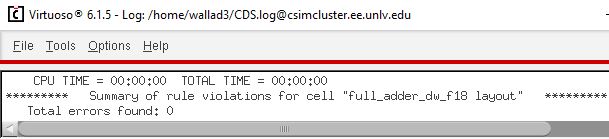
Next you should DRC, extract, and LVS the Full Adder:
Finally, the following schematic and simulation results should be obtained:
This concludes the main content for Lab 6.