Lab 5 - EE 421L

Francisco Mata Carlos

email: matacarl@unlv.nevada.edu

10/10/18


Pre_lab:


Backed-up all files from the lab and course on google drive.

Finished watching Tutorial 3

Lab description:

The goal of this lab is to design, layout and simulate two CMOS inverters. One inverter is using 12u/.6u for the PMOS and 6u/.6u for the NMOS, and for the second inverter, 48u/24u where the devices use a multiplier, M = 4


Below are the schematic and symbol for 12u/6u inverter

http://cmosedu.com/jbaker/courses/ee421L/f18/students/matacarl/Lab%205/inverter_schematic.PNG   http://cmosedu.com/jbaker/courses/ee421L/f18/students/matacarl/Lab%205/inverter_symbol.PNG

Below are the layout, extracted, DRC, and LVS for the 12u/6u inveter

http://cmosedu.com/jbaker/courses/ee421L/f18/students/matacarl/Lab%205/inverter_layout.PNG http://cmosedu.com/jbaker/courses/ee421L/f18/students/matacarl/Lab%205/inverter_extracted.PNG  http://cmosedu.com/jbaker/courses/ee421L/f18/students/matacarl/Lab%205/drc_inverter.PNG

http://cmosedu.com/jbaker/courses/ee421L/f18/students/matacarl/Lab%205/inverter_lvs.PNG

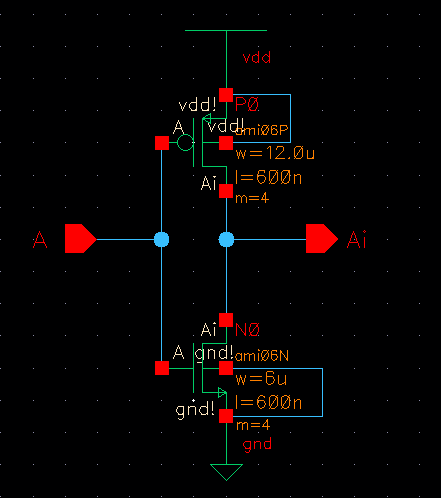
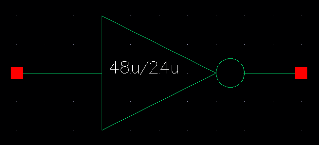
Below are the schematic and symbol for 48u/24u inverter

http://cmosedu.com/jbaker/courses/ee421L/f18/students/matacarl/Lab%205/inverter_multi_schematic.PNG http://cmosedu.com/jbaker/courses/ee421L/f18/students/matacarl/Lab%205/inverter_multi_symbol.PNG

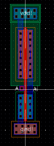
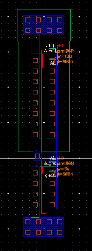
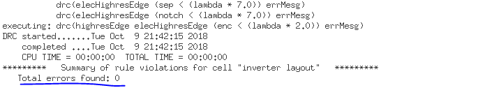
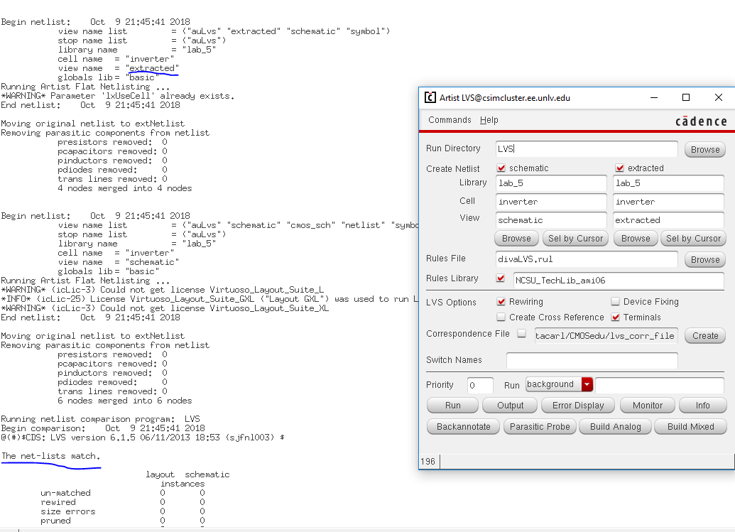
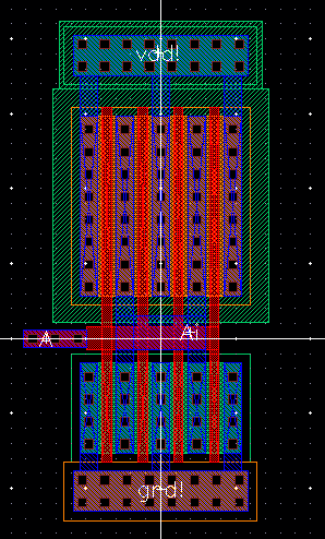
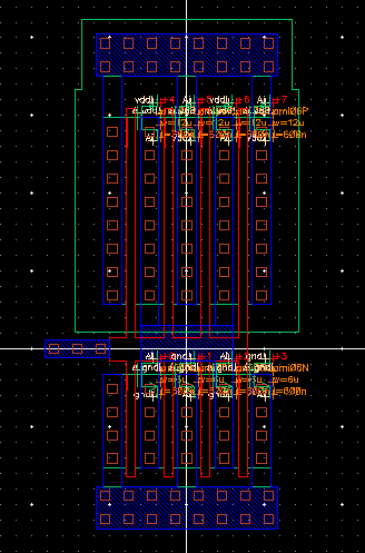
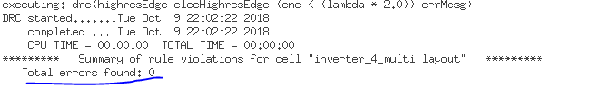
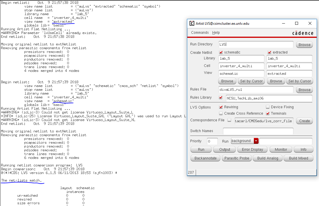
Below are the layout, extracted, DRC, and LVS for the 48u/24u inveter

http://cmosedu.com/jbaker/courses/ee421L/f18/students/matacarl/Lab%205/inverter_multi_layout.PNG  http://cmosedu.com/jbaker/courses/ee421L/f18/students/matacarl/Lab%205/inverter_multi_extracted.PNGhttp://cmosedu.com/jbaker/courses/ee421L/f18/students/matacarl/Lab%205/inverter_multi_DRC.PNG

http://cmosedu.com/jbaker/courses/ee421L/f18/students/matacarl/Lab%205/inverter_multi_lvs.PNG

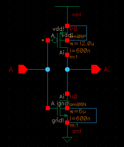
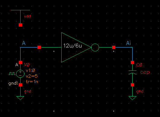
Below are the schematic and simulations for the 12u/6u inveter using Spectre

http://cmosedu.com/jbaker/courses/ee421L/f18/students/matacarl/Lab%205/12u_6u_all_schematic.PNG http://cmosedu.com/jbaker/courses/ee421L/f18/students/matacarl/Lab%205/12u_6u_all_specter.PNG

http://cmosedu.com/jbaker/courses/ee421L/f18/students/matacarl/Lab%205/12u_6u_all_specter_command.PNG

Below are simulations for the 12u/6u inveter using UltraSim

http://cmosedu.com/jbaker/courses/ee421L/f18/students/matacarl/Lab%205/12u_6u_ultrasim.JPG

http://cmosedu.com/jbaker/courses/ee421L/f18/students/matacarl/Lab%205/12u_6u_all_ultrasim_command.PNG

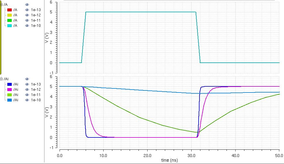
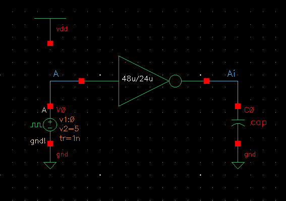
Below are the schematic and simulations for the 48u/24u inveter using Spectre

http://cmosedu.com/jbaker/courses/ee421L/f18/students/matacarl/Lab%205/48u_24u_all_schematic.PNG

http://cmosedu.com/jbaker/courses/ee421L/f18/students/matacarl/Lab%205/48u_24u_all_specter.PNG
http://cmosedu.com/jbaker/courses/ee421L/f18/students/matacarl/Lab%205/48u_24u_all_specter_command.PNG

Below are the simulations for the 48u/24u inverter using UltraSim

http://cmosedu.com/jbaker/courses/ee421L/f18/students/matacarl/Lab%205/48u_24u_all_Ultrasim.PNG

http://cmosedu.com/jbaker/courses/ee421L/f18/students/matacarl/Lab%205/48u_24u_all_ultrasim_command.PNG

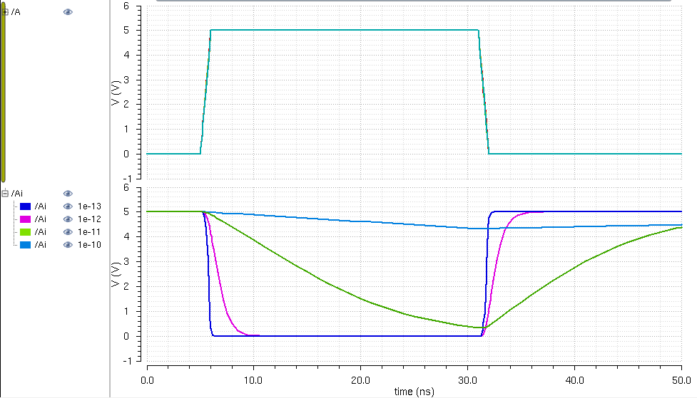
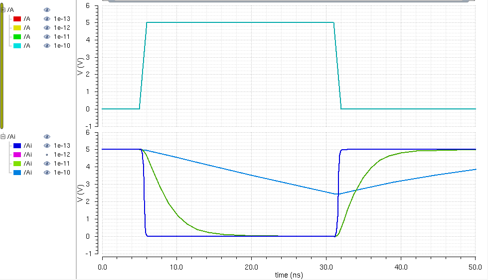
The simulations above show that by increasing the capacitor value, the RC time increases, which causes the output voltage not to be completely inverted as the input switches from 0V to 5V within the time given, or the pulse period.


Layout, schematic, and simulation files can be found here lab5_fmc
Return to student lab reports

Return to labs