Lab 3 - EE 421L
Layout of a 10-bit digital-to-analog converter (DAC)
Lab:
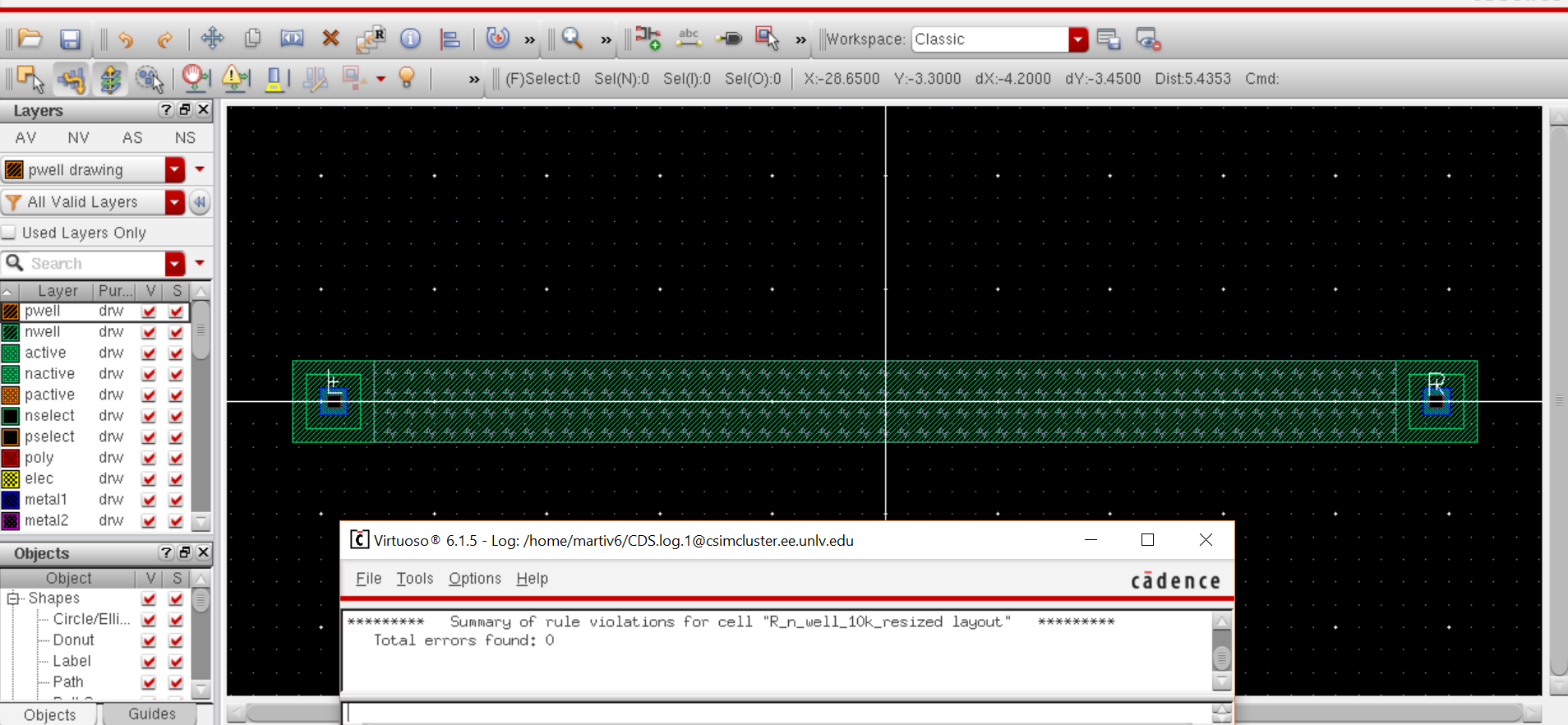
Layout of 10k resistor
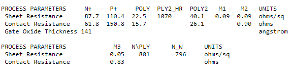
Looking at the parameters of the C5 process, the sheet resistance is 796 ohms/square
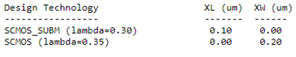
our minimum legnth will be 3.6 um
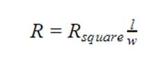
using the equation above and using 10k as our resistor value, plugging the values in gets us our length to be 45.3 um after accounting for it being disivible by lambda.
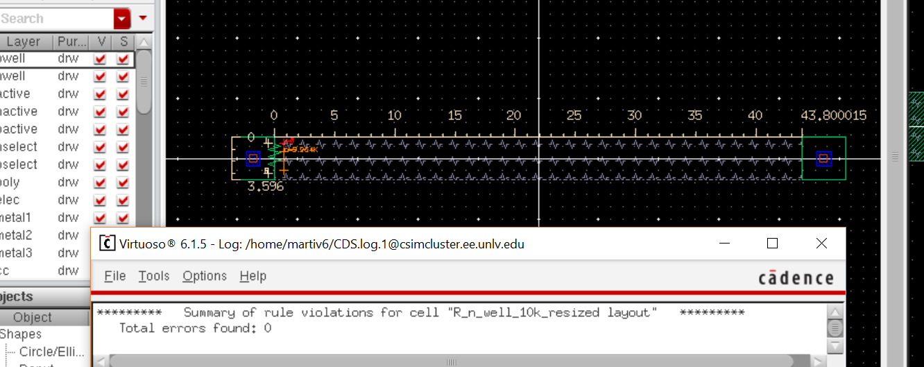
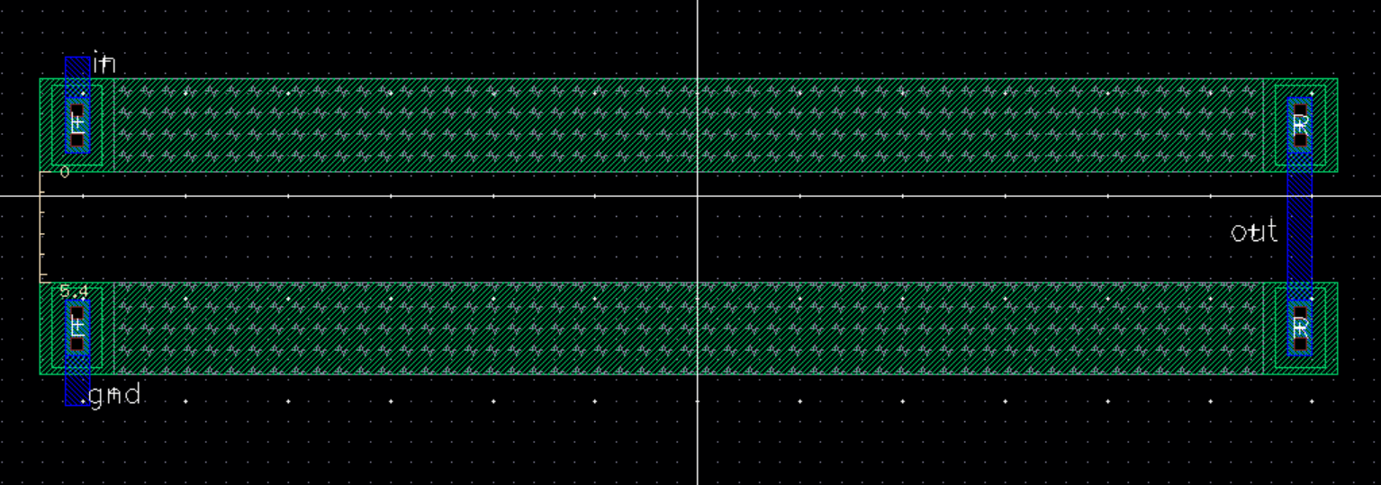
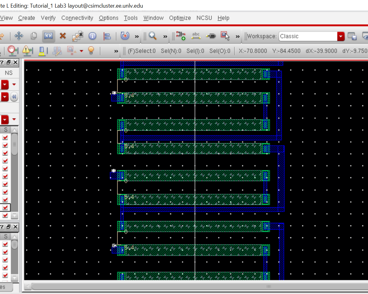
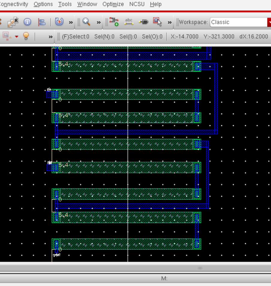
Layout of DAC Using 10k N-Well Resistor
After
seperating the resistors by 5.4 um which is the minimum distance to not
violate any of the C5 proccess I began to stack them with equal
distance between them.
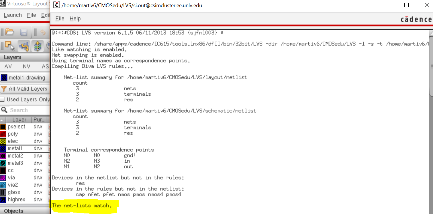
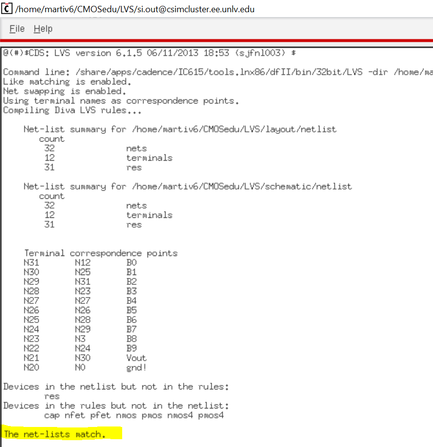
After putting all 31 one of them down and wiring them I DRC it and then ran an LVS with the schematic from lab 2 and got it to match .
I plugged in the layout to the schematic from lab 2 and it got simliar values like before.
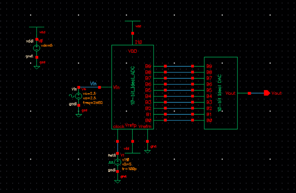
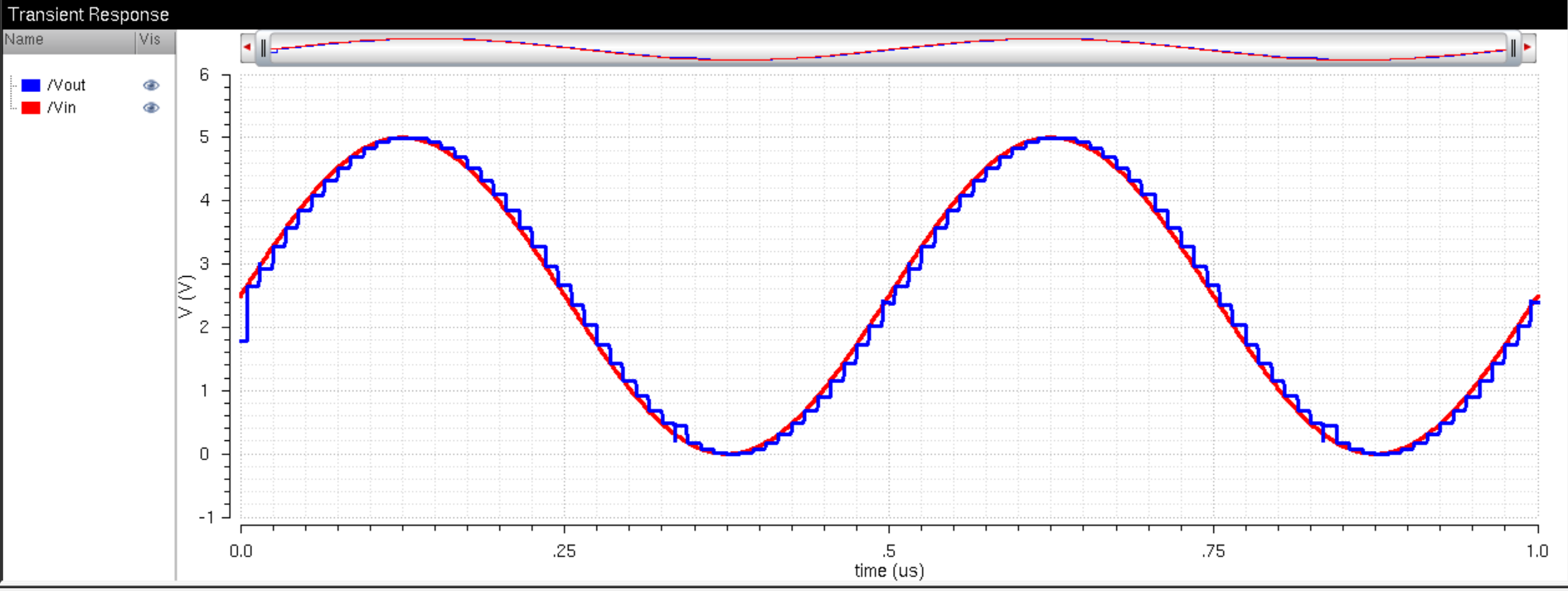
with the layout i created it gave a simliar step ladder shape to the output.