Lab 1 - EE 421L
Authored
by Andy Sam,
sama1@unlv.nevada.edu
8/30/2017
Lab 1 follows the Cadence Tutorial 1 to the 25th image.
1)
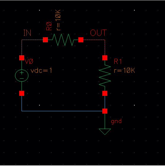
The tutorial has us create a basic voltage divider circuit in Virtuoso
and do a transient analysis using the Spectre tool. Below is a snip of
the schematic.
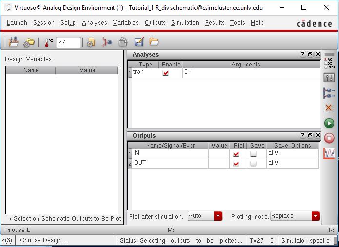
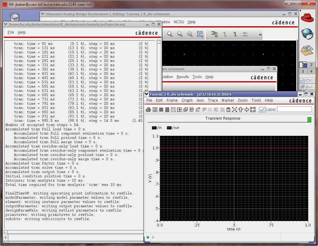
After
creating the schematic, the Analog Design Environment L(ADE L) is
launched. From there a 1 second transient analysis is selected and the
IN and OUT nets are selected to be plotted.
The analysis is ran and a plot is created. Note the background is changed to white for better visibility.
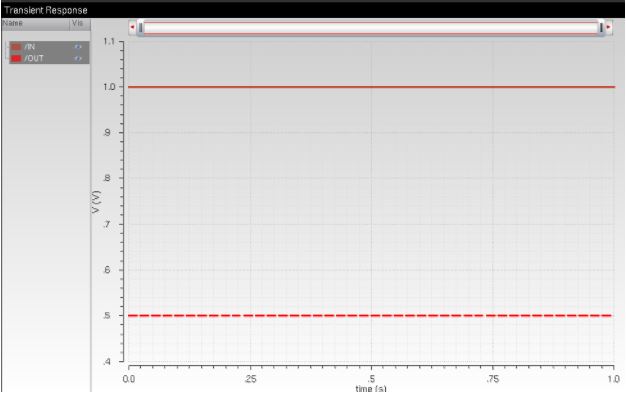
Using the equation for a voltage divider, we can verify our plot is correct:
2) I will be using my local drive on my personal computer as primary storage.
Google Drive will be used as backup storage. When uploaded to Google Drive, time stamps are created for day of creation and modification. Each figure will be named in order using the following naming
convention: L#_Fig#.extension. The figure number will is determined by
time of creation. Equations and work for the lab will be saved as
images, along side figures, but labeled as equations(EQ). Equations
will either be done by hand and scanned in or created as an image in a
seperate editor.
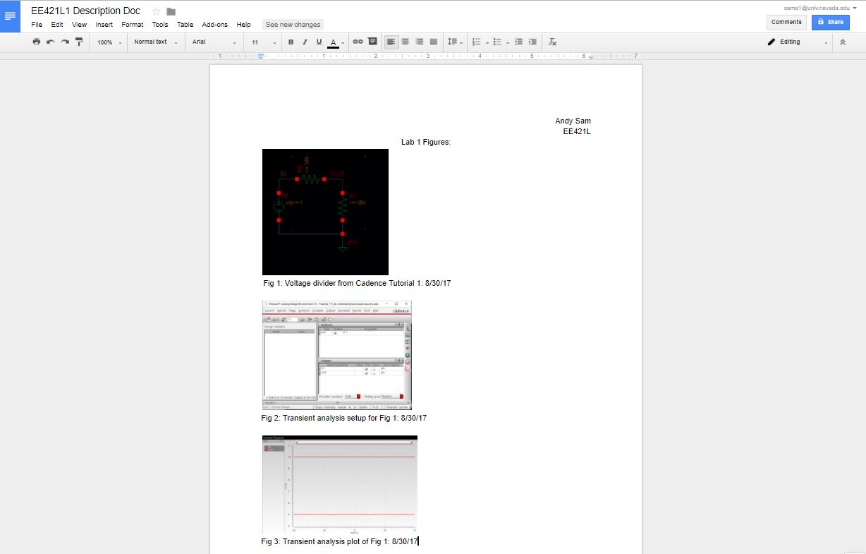
On top of this, I will create a description file that will describe each figure/equation as well as their date of creation.
Return to EE421 Labs