Lab 2 - EE 421L 

Authored by Sharyn Miyaji,

Email: miyajis@unlv.nevada.edu

Wednesday, September 14, 2016


Pre-Lab work:


First, download lab2.zip to your desktop to receive the files for Lab 2.  Then upload the lab2.zip into the CMOSedu folder on MobaXterm. Once the zip file is uplaoded, the type in the command unzip lab2.zip to unzip the file and then add DEFINE lab2 $HOME/CMOSedu/lab2 to the cds.lib file in the CMOSedu folder.  Open up Cadence by typing in virtuoso & and make sure to be in the CMOSedu directory.  The Library Manager should pop up when Cadence opens up and lab2 should be listed in the library.  If the Library Manager does not open, then click on the Tools tab in the Cadence commmand window.  Select lab2 library and open up the schematic of sim_Ideal_ADC_DAC, which is shown below.


http://cmosedu.com/jbaker/courses/ee421L/f16/students/miyajis/Lab%202/PreLab_Schematic.JPG


When the schematic opens up, click on the Launch tab and select ADE L to run the simulation.  When the ADE L window opens up, click on the Session tab and select Load State.  Cellview should be selected on the load state option and click OK.  Then click on the green button on the right side of the ADE L window to run the simulation of the sim_IDEAL_ADC_DAC schematic as shown below.  
   

http://cmosedu.com/jbaker/courses/ee421L/f16/students/miyajis/Lab%202/PreLab_Simulation.JPG


An analog signal from the voltage source is being inputted into the 10-bit ADC, which converts an analog signal to a digital signal by breaking it down into 10-bits.  Those 10-bits then go through the DAC and creates an output analog signal, which is displayed above.  The results of the input and the output voltage are similar, but there are small errors in the output voltage simulation. The causes of those errors are the number of bits in the converters.  As seen in the equation below, N represents the number of bits in the converter and VDD is the voltage from the source.  LSB is the least significant bit, which is also the difference between the input voltage and the output voltage.  In the schematic, the VDD is 5 volts and the number of bits used in the DAC is 10 bits; therefore, the LSB is 4.88mV.


http://cmosedu.com/jbaker/courses/ee421L/f16/students/miyajis/Lab%202/LSB_Calculation.JPG


Lab work:

 
Designing a 10-bit DAC
 
The purpose of the lab is to build a 10-bit DAC using n-well 10k resistors only in Cadence and using the DAC created for different tests.  First, a schematic of one bit in a DAC is built by building two 10k resistor in series and one 10k resistor in parallel as shown below on the left.  Then the schematic is converted into a symbol, as seen on the right, by clicking on the Create tab, Cellview, and From Cellview.


http://cmosedu.com/jbaker/courses/ee421L/f16/students/miyajis/Lab%202/DACresistors.JPG             http://cmosedu.com/jbaker/courses/ee421L/f16/students/miyajis/Lab%202/DAC_resistor_symbol.JPG

 
Next, my 10-bit DAC schematic is built using the symbol created above with an additional 10k resistor added to the bottom of the DAC.  Again, the schematic is converted into a symbol to make a simplified version of a DAC.
 
http://cmosedu.com/jbaker/courses/ee421L/f16/students/miyajis/Lab%202/SM_10bit-DAC-schematic.JPG        http://cmosedu.com/jbaker/courses/ee421L/f16/students/miyajis/Lab%202/SM_10bit-DAC.JPG
 
Calculating Output Resistance of a DAC
 
Below is the calculation of the output reisistance of the DAC by combining resistors that are in series and parallel, which result in the value of one resistor.
   
http://cmosedu.com/jbaker/courses/ee421L/f16/students/miyajis/Lab%202/Resistor_Calculation.JPG
   
Delay, Driving a Load
   
To create a delay using a DAC, a 10 pF capacitor is added in parallel to the DAC with the B9 pin attached to a pulse source and the rest of the pins grounded as shown below.  As shown below, the pulse source being used is 0 to 5 volts, so the expected voltage at the time delay is 1.25 volts, which is a fourth of the input voltage.  A fourth of the voltage is expected because the ouput voltage is half of the input voltage and the time delay is at 50% of the output voltage.  To calculate the time delay, it is 0.7*R*C, where the reisistor is 10k and the capacitor is 10pF; therefore, the time delay is 70 ns.
   
http://cmosedu.com/jbaker/courses/ee421L/f16/students/miyajis/Lab%202/Delay_schematic.JPG
 
http://cmosedu.com/jbaker/courses/ee421L/f16/students/miyajis/Lab%202/Delay_simulation.JPG
   
Simulations
 
Before doing any simulations, copy sim_Ideal_ADC_DAC in the same library, but rename it
sim2_Ideal_ADC_DAC, so the copied version can be used for editting.  Open up sim2_Ideal_ADC_DAC schematic, delete the DAC, and replace it with the DAC that was created earlier as shown below.  The simulation should look like the one below the schematic.
   
http://cmosedu.com/jbaker/courses/ee421L/f16/students/miyajis/Lab%202/sim2_Ideal_ADC_DAC_schematic.JPG
 
http://cmosedu.com/jbaker/courses/ee421L/f16/students/miyajis/Lab%202/sim2_Ideal_ADC_DAC.JPG

Using the same schematic, we attached a resisitive load, a capacitive load, and an RC load, where the resistor is 10k and the capacitor is 10 pF, to see how it affects the simulations.
   
Using a resisitive load:
   
http://cmosedu.com/jbaker/courses/ee421L/f16/students/miyajis/Lab%202/schematic_10k.JPG        http://cmosedu.com/jbaker/courses/ee421L/f16/students/miyajis/Lab%202/simulation_10k.JPG
   
Using a capacitive load:
 
http://cmosedu.com/jbaker/courses/ee421L/f16/students/miyajis/Lab%202/schematic_10pF.JPG        http://cmosedu.com/jbaker/courses/ee421L/f16/students/miyajis/Lab%202/simulation_10pF.JPG

Using an RC load:
   
http://cmosedu.com/jbaker/courses/ee421L/f16/students/miyajis/Lab%202/schematic_10k_10pf.JPG        http://cmosedu.com/jbaker/courses/ee421L/f16/students/miyajis/Lab%202/simulation_10k_10pf.JPG


Explain what happens if the DAC drives a 10k load. If the DAC drives a 10k load, it causes the output voltage to be half of the input voltage because the extra resistor creates an additional voltage divider.


Discuss what happens if the resistance of the switches isn't small compared to R.  If the resistance of the switches isn't small compared to R, it will cause the output voltage to be lower.  With the switch acting as a larger resistor, it will be in series with the other two resistors that are already implemented in the DAC; therefore, it increases the resistance value.


Back Ups


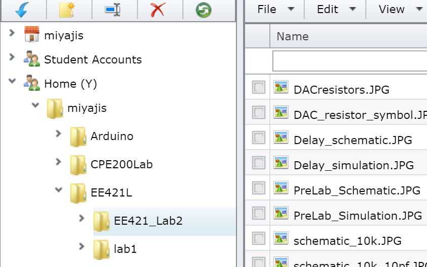
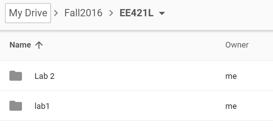
I will back up my files for this lab in my student drive and UNLV Google drive.


http://cmosedu.com/jbaker/courses/ee421L/f16/students/miyajis/Lab%202/Backfile1.JPG        http://cmosedu.com/jbaker/courses/ee421L/f16/students/miyajis/Lab%202/Backfile2.JPG


Return to EE421L Labs