Lab 5 - EE 421L
Authored
by Ja Manipon
maniponj@unlv.nevada.edu
10/5/16
Lab Files
Pre-Lab
- Back-up all of your work from the lab and the course.
- Go through Tutorial 3 seen here.
Post-Lab
- Draft schematics, layouts, and symbols for two inverters having sizes of:
- 12u/6u (= width of the PMOS / width of the NMOS with both devices having minimum lengths of 0.6u)
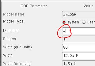
- 48u/24u where the devices use a multiplier, M = 4 (set along with the width and length of the MOSFET, image)
- Layouts below.
- Power runs on the top of the cell via metal1 and ground is run on the bottom of the cell also via metal1
- Power (vdd!) is connected to the n-well using the ntap cell
- Ground (gnd!) is connected to the p-substrate using the ptap cell
- Running power and ground with a single row of contacts
- Your schematics should have two pins, e.g., A and Ai
- Your layouts should have 4 pins: A, Ai, vdd!, and gnd! (note how lowercase letters are used for power and ground)
- Your
lab reports should document your efforts and results including showing
that the extracted layouts and schematics LVS correctly
- Zip up these cells in a directory call lab5_rjb.zip (last two or three letters are your initials) and link to your lab report
- Using SPICE simulate the operation of both of your inverters showing each driving a 100 fF, 1 pF, 10 pF, and 100 pF capacitive load
- Comment, in your report, on the results
- Use UltraSim (Cadence's fast SPICE simulator for larger circuits at the cost of accuracy) and repeat the above simulations
- Use Setup -> Simulator/Directory/Host and select UltraSim as seen below
- You'll also have to point to the MOSFET models again as seen below
- Note that UltraSim only performs transient simulations (not AC, Noise, DC, operating point, etc.)
- Not knowing this last item will lead to wasted time if trying to use UltraSim exclusively for simulations
Layout and Schematic of 12u/6u and 48u/24u Inverters
| 12u/6u | 48u/24u | Details |
| Schematic |  |  | - Here I created the inverter for both the sizes. I made sure I connected the drains together and connected the source and body of
the PMOS to vdd and the source and body of the NMOS to gnd. Input A was
connected to the gates and output Ai was connected to the drains
|
| Layout |  |  | - With
the layout, I designed it according to the previous schematic. I made
sure on the wider inverter I connected all the drains, gates and
sources to the according pins.
|
| Extracted |  |  | - This
is showing all the NMOS and PMOS transistors in the extracted view.
From the wider inverter, there are multiple transistor due to the
parameter of the multiplier being changed to 4
|
| DRC |  |  | - Both had no errors in the DRC
|
| LVS |  |  | - Both netlists matched with the layout and extracted cell views
|
Simulations on 12u/6u and 48u/24u Inverters
| 12u/6u | 48u/24u | Details |
| Symbol |  |  | - I created a symbol for the previous schematics shown above and labeled them accordingly
|
| Schematic w/ Symbol |  |  | - With the symbols created, I attached them to a simulation schematic with vpulse source and capicator with a variable.
|
| Cap = 100f(spectre) |  |  | - From the first capacitor, we can see that the output is invertering as it should
|
| Cap = 1p(spectre) |  |  | - Once
we raised the capacitor, there slope of the output voltage is getting a
little smaller but is not as noticable with the wider inverter
|
| Cap = 10p(spectre) |  |  | - When
the capacitor was raised again, both inverters have a significant
change slopes. The smaller inverter's output voltage does not even
reach 0V within the vpulse
|
| Cap = 100p(spectre) |  |  | - The
capacitor is raised again for the last time and both inverters have a
significant change in their outputs. Both barely invert the output
below 1V
|
| Cap = 100f(ultrasim) |  |  | - Both the simulations are repeated in ultrasim, which is Cadence's faster SPICE simulator and meant for larger circuits at the cost of accuracy.
- From this simulation, the results are very similar from the first
|
| Cap = 1p(ultrasim) |  |  | - The results are similar to the spectre sim
|
| Cap = 10p(ultrasim) |  |  | - These ultrasim simulations have similar outputs but a little off to the previous
|
| Cap = 100p(ultrasim) |  |  | - The last ultrasim simulation again produces similar output to the previous one
|
Return to EE 421 Labs