Lab 5 - EE 421L Fall 2015
Design, layout, and simulation of a CMOS inverter.
Zip folder containing Lab5 files found here.
The purpose of this tutorial is to draw the schematic, symbol, and
layout of a CMOS inverter.
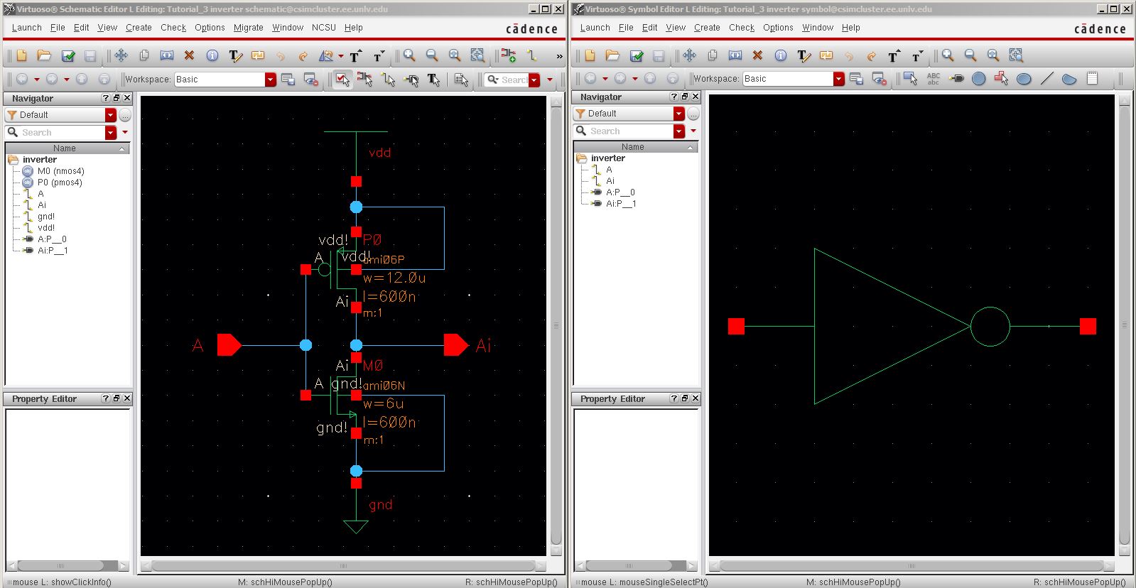
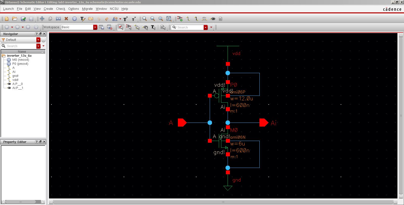
1. Here is the draft
of the inverter using an NMOS of 6u/600n and a PMOS of 12u/600u, and 2 pins A
and Ai. Also after the schematic was completed
a symbol was created.
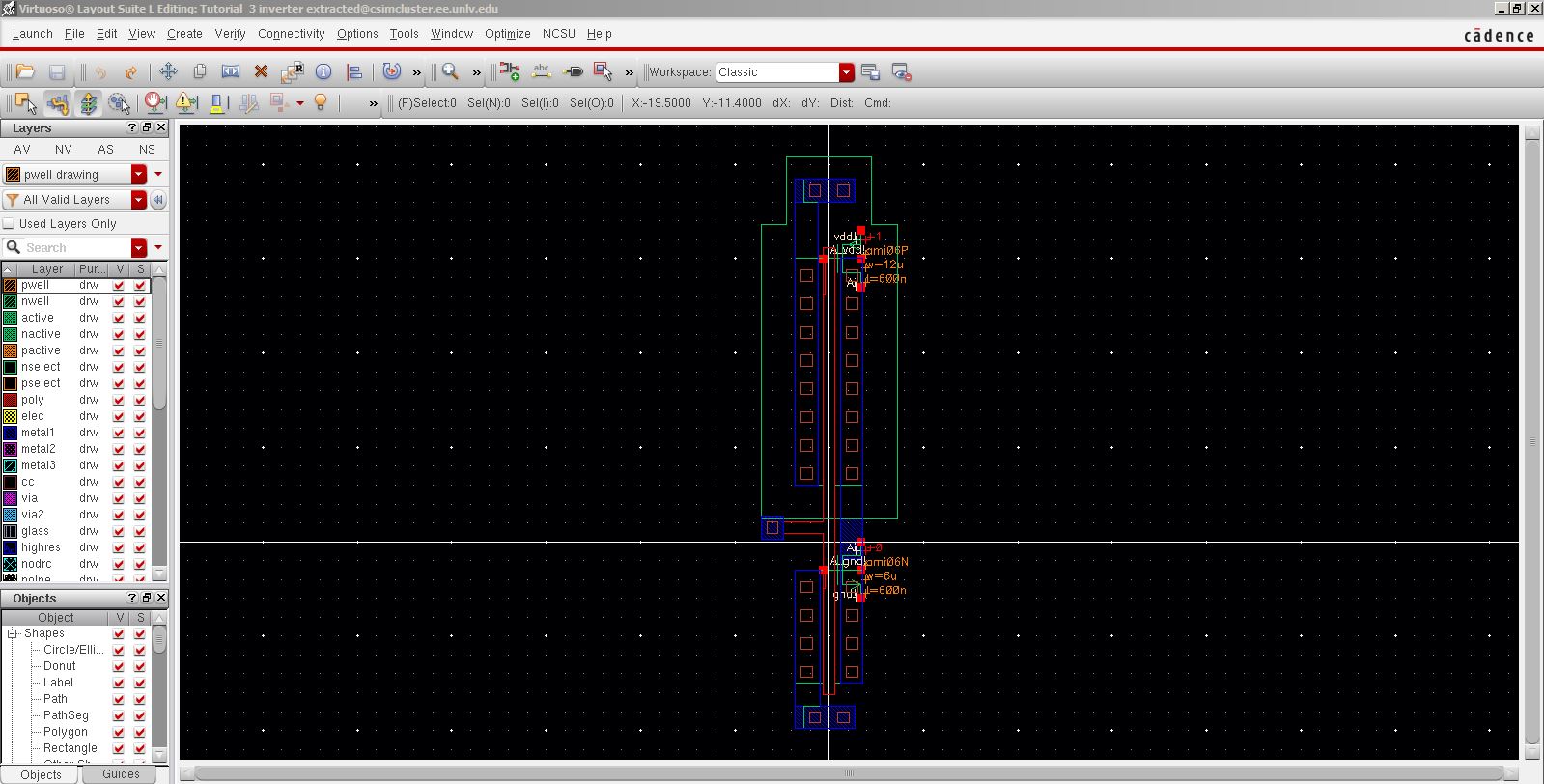
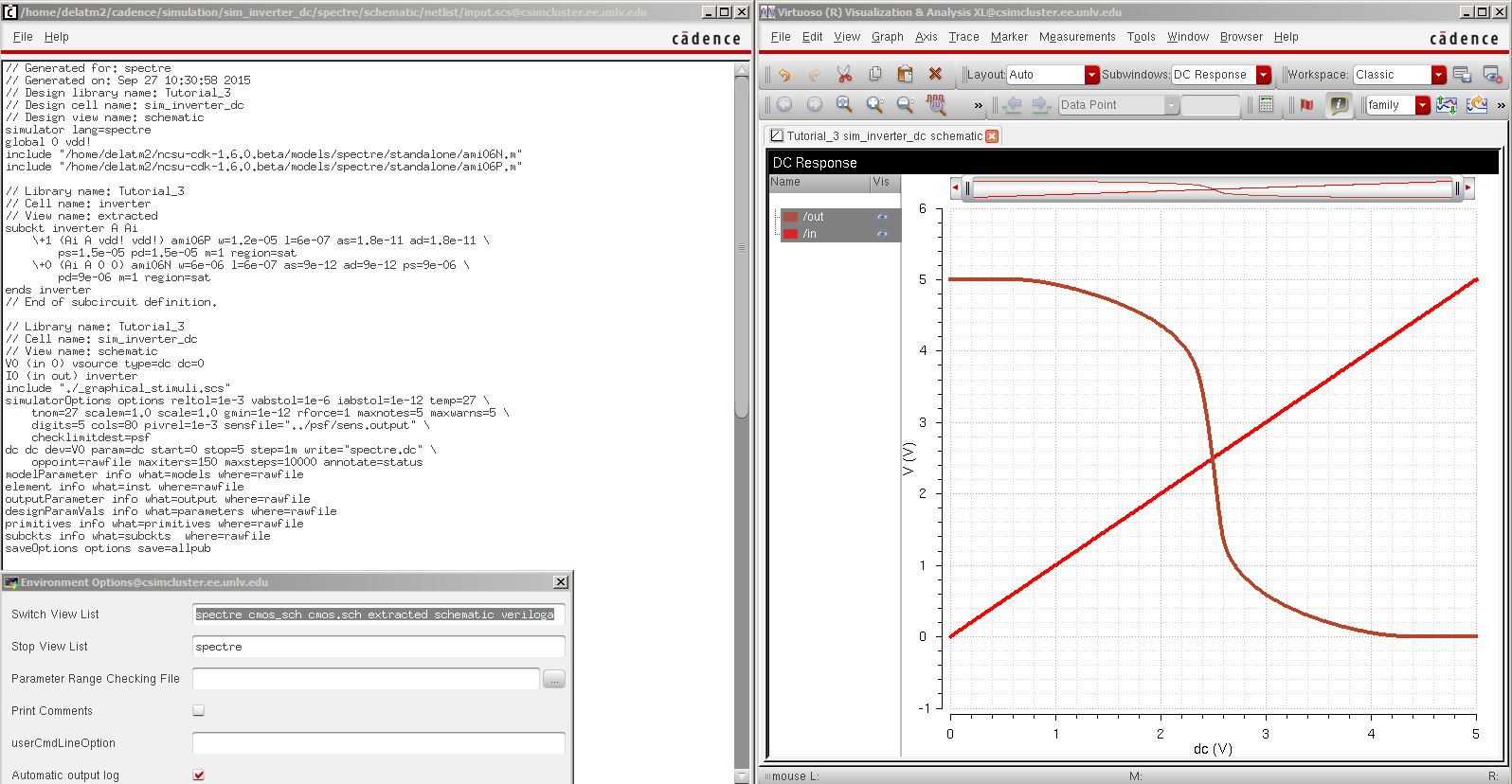
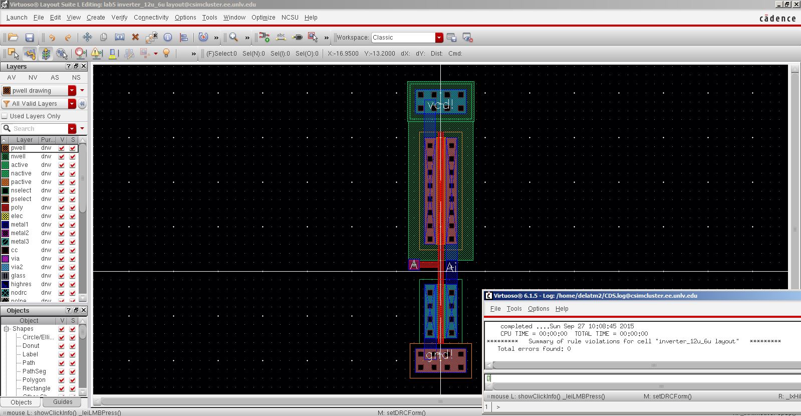
2. Layout view for the inveter and DCR.

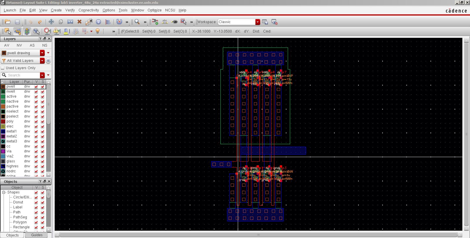
3. Extracted view.
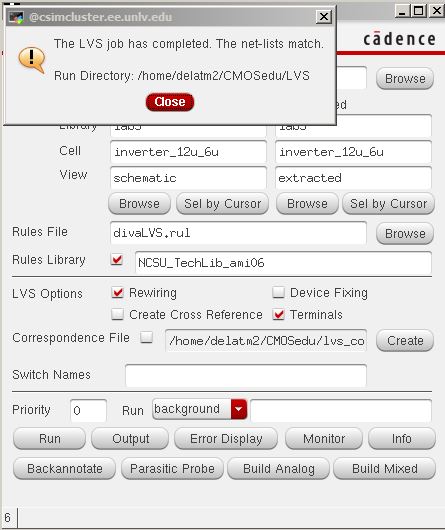
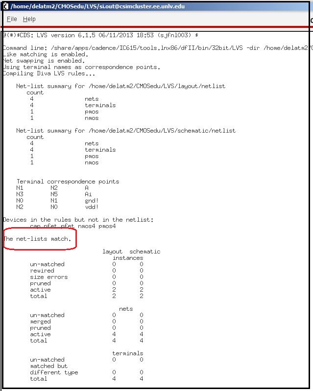
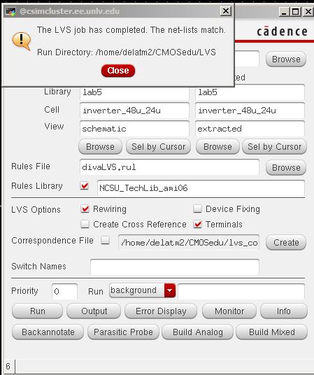
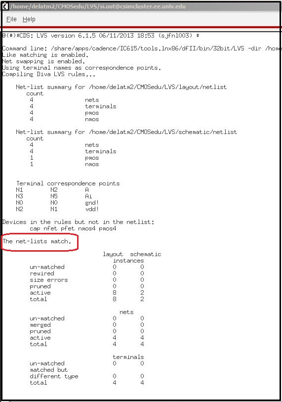
4. LVS with no errors.


This concludes Tutorial 3.
Post-Lab
1. The 12u/6u Inverter.
a. Schematic view.
b. Symbol view.

c. Layout and DRC.
e. Extracted view.

d. LVS with no errors.
Simulations of the 12u/6u inverter using spectre.
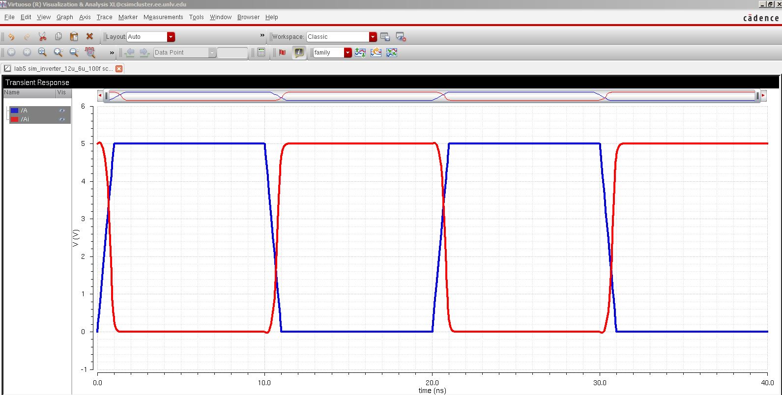
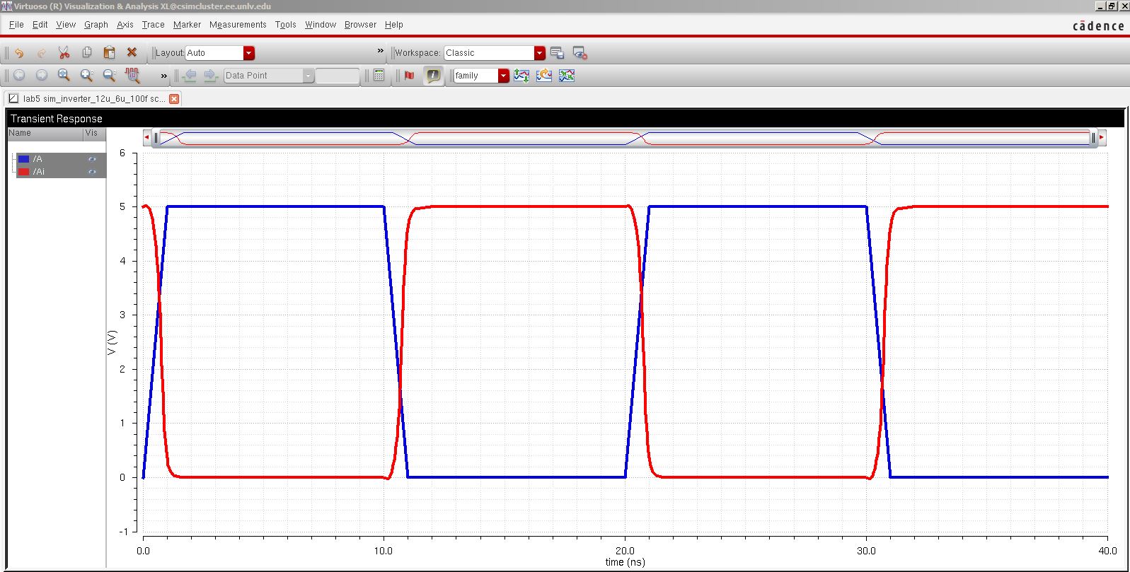
a. Capacitve load 100f f. Because of the small capacitance the output and input are almost identical.
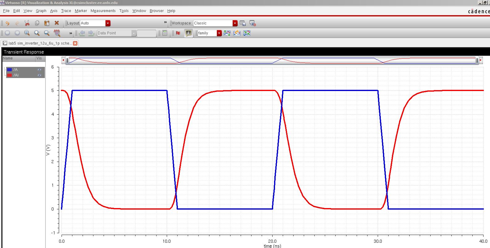
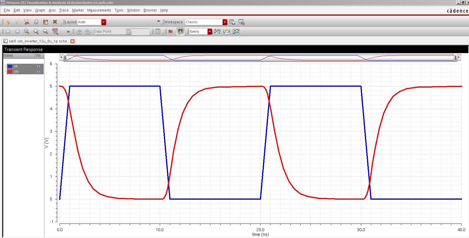
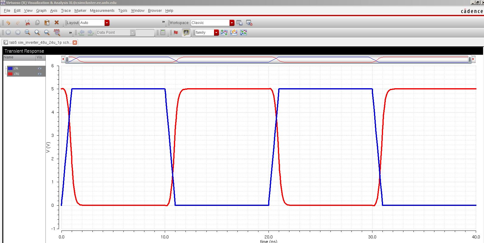
b. Capacitve load 1p f. As the capacitance increases the output gets distorted. It takes more time to charge and disccharge the capacitor.
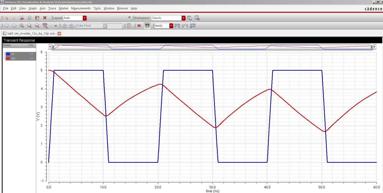
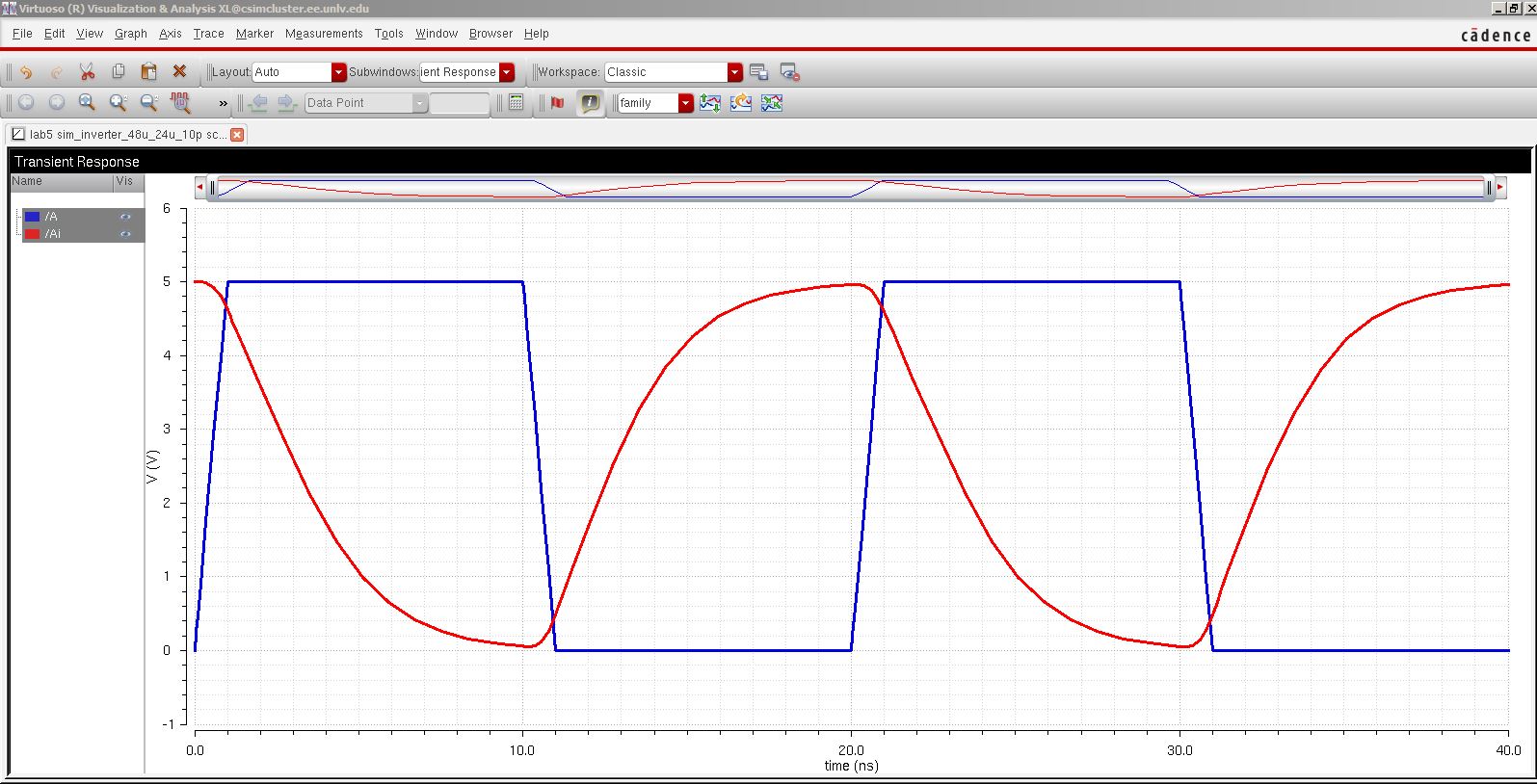
c. Capacitve load 10p f. The capacitor is too big not enough time to discharge and charge properly.
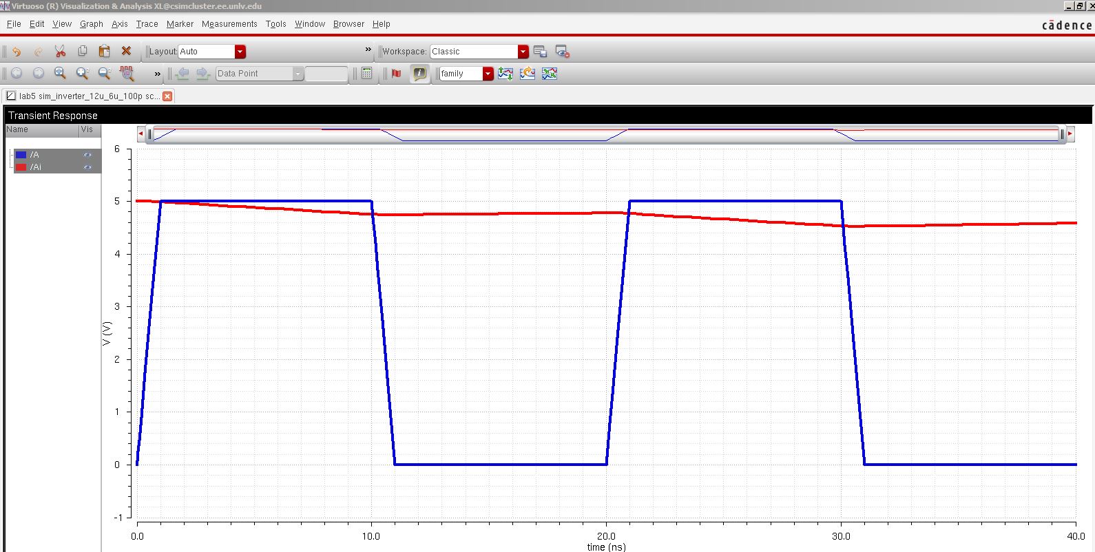
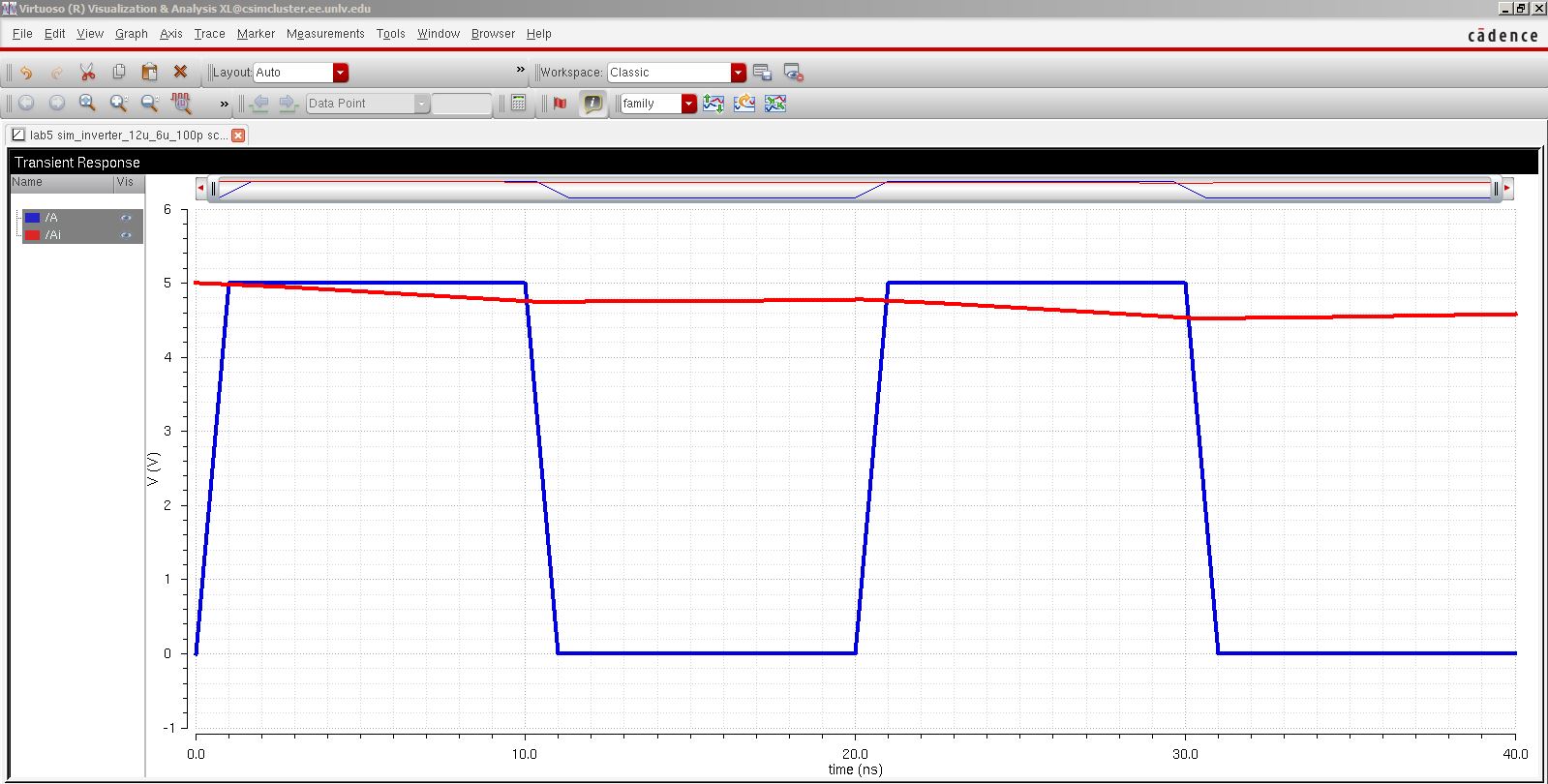
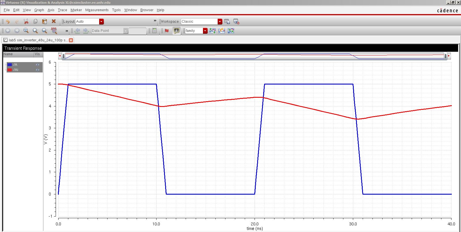
d. Capacitve load 100p f. The capacitor is too big not enough time to discharge.
Simulations of the 12u/6u inverter using ultrasim.
a. Capacitve load 100f f. This simulator is much faster than spectre but less accurate, we can see this effect on the output's peak.
b. Capacitve load 1p f.
c. Capacitve load 10p f.

d. Capacitve load 100p f.
1. The 48u/12u Inverter.
a. Schematic and symbol view.

b. Extracted view.
c. Layout and DRC.

d. LVS with no errors.
Simulations of the 48u/12u inverter using spectre.
a. Capacitve load 100f f. Because of the small capacitance the output and input are almost identical.

b. Capacitve load 1p f. Because of the small capacitance the output and input are almost identical.
c. Capacitve load 10p f. As the capacitance increases the output gets distorted. It takes more time to charge and disccharge the capacitor.
d. Capacitve load 100p f. The capacitor is too big not enough time to discharge and charge properly.
Simulations of the 48u/12u inverter using ultrasim.
a. Capacitve load 100f f. This simulator is much faster than spectre but less accurate, we can see this effect on the output's peak.

b. Capacitve load 1p f. This one the output is not as square as the spectre's simulation.

c. Capacitve load 10p f.

d. Capacitve load 100p f.

Backing up my work.
1. A zip folder will be created Lab2.
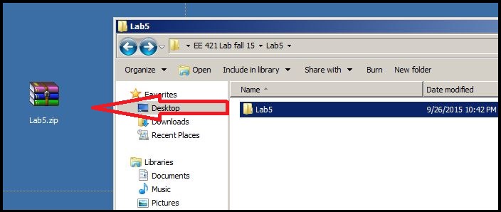
2. Then the zipped folder will be store on my google drive.