Lab 1 - ECE 421L
Authored
by Leanna Guevara,
Email: guevaral@unlv.nevada.edu
September 8, 2014
Laboratory Interoduction, generating/posting html lab reports, installing and using Cadence
For
this lab report we must access Cadence Design System. The process for
installation and setting up the libraries can be found here.
Once
the users csimcluster server has been set up the user will be able to
access Cadences. To do so the user must go to the CMOSedu directories
(type cd CMOSedu) and start Cadence's virtuoso (type virtuoso &).

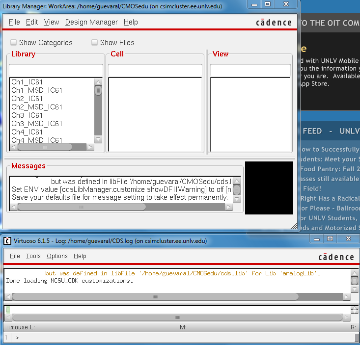
In a few seconds the Cadence Library Manager should appear.
For this tutorial the user will create a new library by going to File->New->Library
Name the library Tutorial_1, select Attach to existing tech library and AMI 0.60u C5N (3M, 2P, high-res) as seen below.

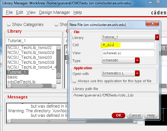
After creating the library go back to the Library Manager and create a new cell by selecting File->New->Cell.
For this cell we used the label R_div
Now the user can start creating the schematic. The 'i' key which will bring up the Instance window from which we can find our components. Not that the value of the resistor was changed from 1K Ohms to 10K Ohms.
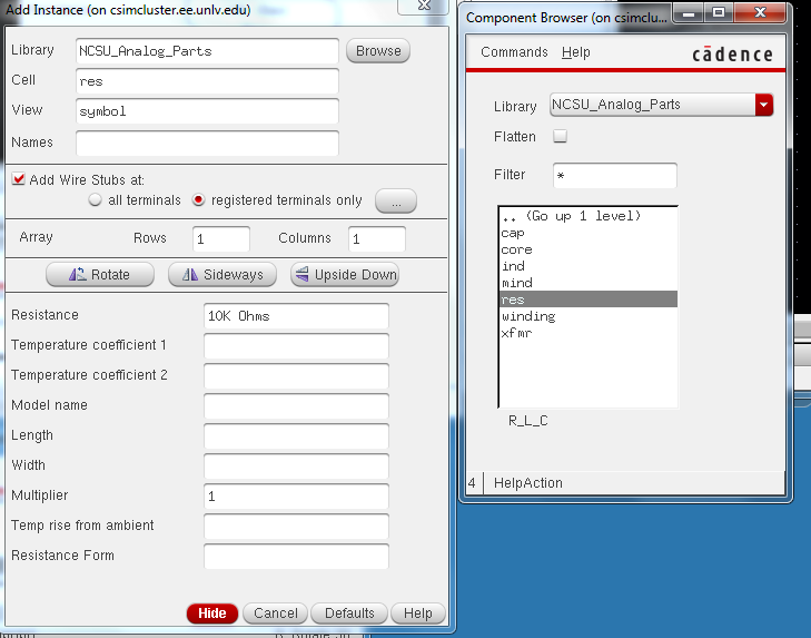
Once the component has been selected we can start placing the parts. To rotate the parts we can right click the mouse.

Shortcuts to know
| Keys | Purpose |
| i | Inductance- to select components |
| w | Wire |
| l (lowercase L) | Label |
| q | Object- to make adjustment of values |
| f | Fit schematic |
| shift+z | Zoom in |
| control+z | Zoom out |
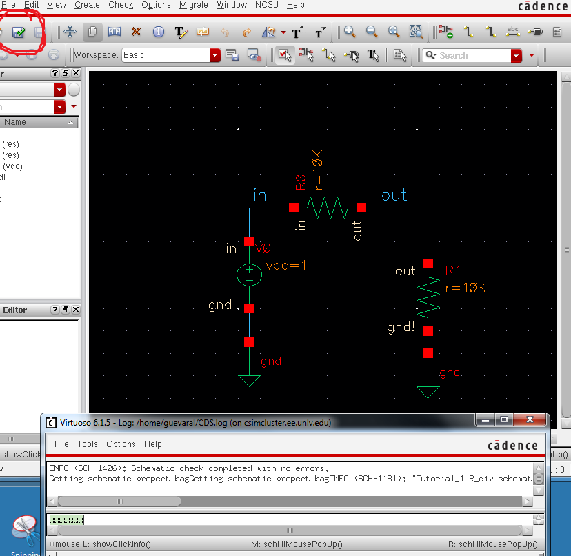
Once the schematic below is created click check and save and make sure there are no errors.
Now the user can prepare for the simulation by clicking Launch->ADE L
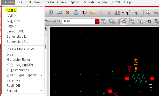
The
window below should pop up. Analysis and Outputs will originally be
blank the simulation will not work correctly until we insert the
following. For the outputs go Outputs->To Be Plotted->Select on Schematic then click the input wire and the output wire.

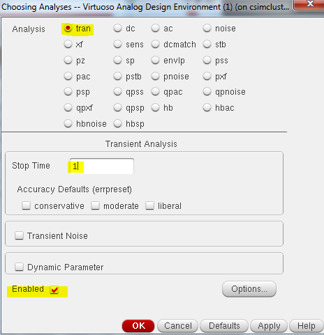
To select Analysis click Analyses->Choose. The window below will appear, for this tutorial we will do a transient analysis with a 1 second stop time.
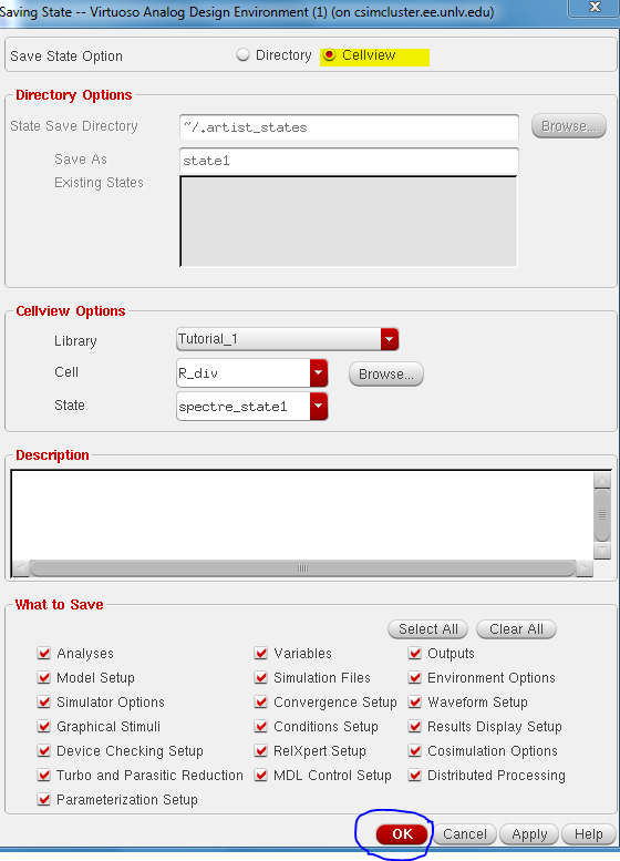
The schematic is now ready for simulation. Save the set up by clicking Session->Save State. Make sure to select Cellview for the Save State Option and Ok.
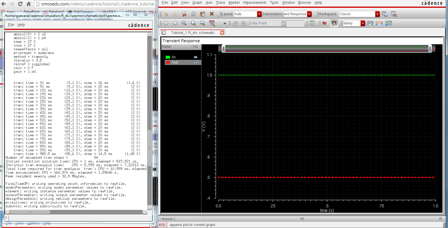
To run the simulation click 
The results of the simulation should look like
End of Lab 1
Since accidents happen the user should always have a back up of the files created. From MobaXterm the user can drag the tutorial_1 file (located in CMOSedu folder) to the desktop, zip the file and email to themselves.
Return to EE 421L Labs