Lab 7 - ECE 420L
Authored
by Stephanie Silic
silics@unlv.nevada.edu
March 29th, 2017
Lab Description
Design of an audio amplifier
- Design
an audio amplifier (frequency range from roughly 100Hz to 20kHz )
assuming that you can use as many resistors, ZVN3306A transistors, and
ZVP3306A transistors as you need along with only one 10uF
capacitor and one 100uF capacitor. Assume that the supply voltage is 10V, the input is an audio signal from an MP3 player (so your amplifier should have at least a few kiloohms input resistance), and the output of your design is connected to an 8 Ohm speaker (so ideally the output resistance of your amplifier is less than 1 Ohm).
Lab report should include:
- thoughts
on the design of the amplifier including hand calculations. (A good
place to start is with the push-pull amplifier characterized in lab 6.)
- Simulation of design
- Build and testing results of design.
- performance of the design including power dissipation, output swing, input resistance, output resistance.
Lab Report
An audio amplifier must take a small signal from music (say an mp3
plalyer), which has such a small magnitude that it is not audible to
the human ear, and amplify the signal to something we can hear through
a speaker.
For this design process,
I begin by simulating the single push-pull amplifier to understand
what's going on. The circuit used was given in the prelab and can be
found in lab7_sims.zip.
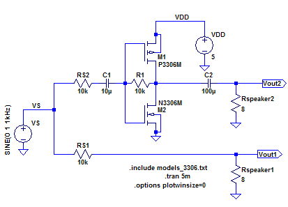
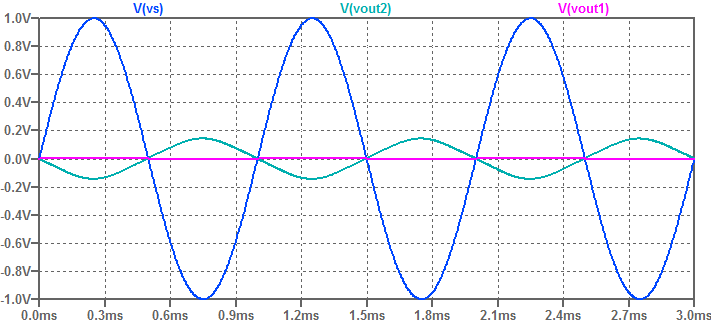
Vout1 shows what happens when the signal is directly connected to the 8
ohm speaker. Most of the voltage is dropped accross the much bigger 10k
source resistance, so the output is barely detectable.
Vout2
shows what happens when the signal is amplified by a push-pull
amplifier. The gain of the push-pull amplifier with no load attached
was calculated in lab 6 as follows:
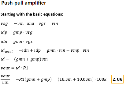
In
the amplifier simulated above, the value of R1 is 10k, which would mean
the push-pull amplifier would have a gain of about 280 under no load.
As
noted in the design specifications, the output resistance of the
amplifier should be much less than 8 ohms. This is so that most of the
output voltage is dropped across the output (the 8 ohm speaker) rather
than the output resistance of the amplifier.
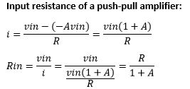
The calculation for the input resistance of the push-pull amplifier is as follows:
How can we reduce the output resistance?
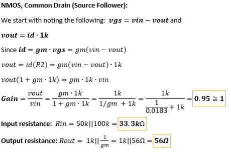
Previoius
students have done this by noticing that the Common Drain amplifier, or
a source follower, has an output resistance much smaller than other
amplifier topologies. Since the output resistance is calculated as
follows (once again, from lab 6)
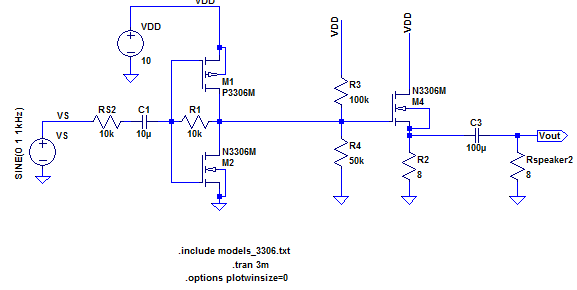
The circuit would be the following:
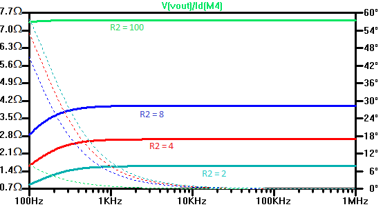
Simulating the Rout of the circuit shown above, varying R2:
With
a smaller resistor, the output resistance goes down. Ideally, this
resistance is nearly 1 for an 8 ohm speaker so that enough voltage
drops across the speaker.
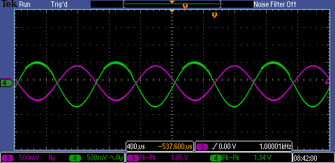
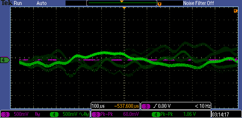
Building
and testing this circuit with a 3.3 ohm R2 value, the smalleset we have available, the gain was high enough to hear a moderate
volume from the speaker. The following screenshot shows the operation
of the circuit at 1kHz, with the speaker attached:
In
this lab, however, we were making use of a 25 ohm speaker. Because of this, the
push-pull amplifier by itself was able to work better than trying to use the source follower to decrease output resistance.
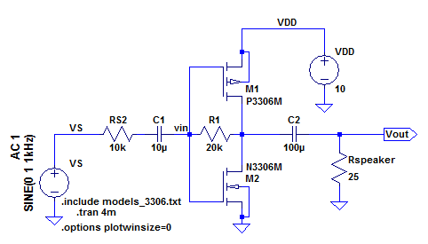
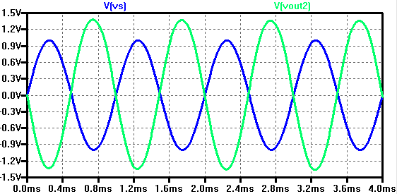
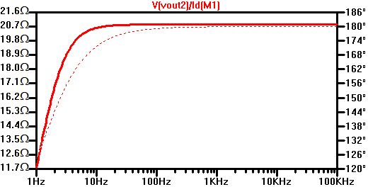
Here
is the circuit and simulation of the push-pull amplifier with a 25 ohm
load for the speaker, and a 20k feedback resistor for higher gain:
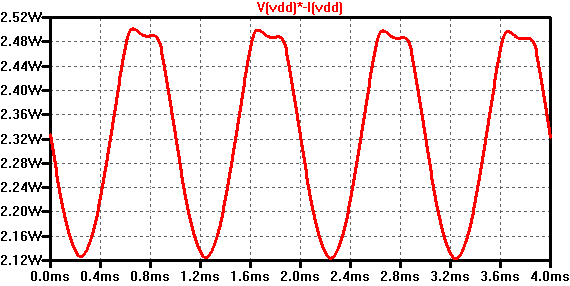
The
power consumed by the circuit is found by multiplying the input voltage
by the total current drawn by the circuit, or the current through the
VDD source. For this circuit, the power drawn turns out to be about 2.3
Watts, which is acceptable for the speaker.
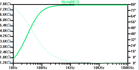
The Rin and Rout values are simulated as well:
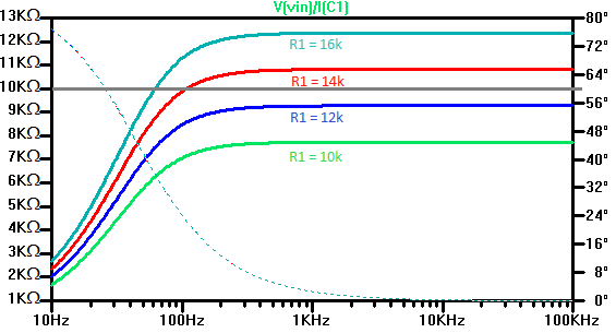
Since we want a higher input resistance, a parametric simulation varying R1 was done to see the change in input resistance:
Initially,
a 10k ohm input resistance was selected, but after testing this
circuit, I used a higher resistor to increase the gain.Since a high input resistance is desired, this was deemed acceptable.
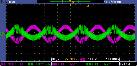
Building and testing the circuit, the following oscilloscope image shows the output swing of the amplifier:
Oscilloscope screenshot while playing music:
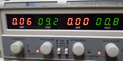
The
power drawn by the circuit is the current drawn multiplied by the input
voltage. The power consumption is about 0.06Ax9.2V .5 Watts as shown
here. The current however, did stay mainly at about 100mA, rather 60mA
as shown in the picture of the power supply, which in that case would
be 9.2Vx0.11A = 1.01 Watts.
Return to my labs