
Lab 5 - EE 420L
Lab Work
Again, this lab will utilize the LM324 op-amp (LM324.pdf).
For the following questions and experiments assume VCC+ = +5V and VCC- = 0V.
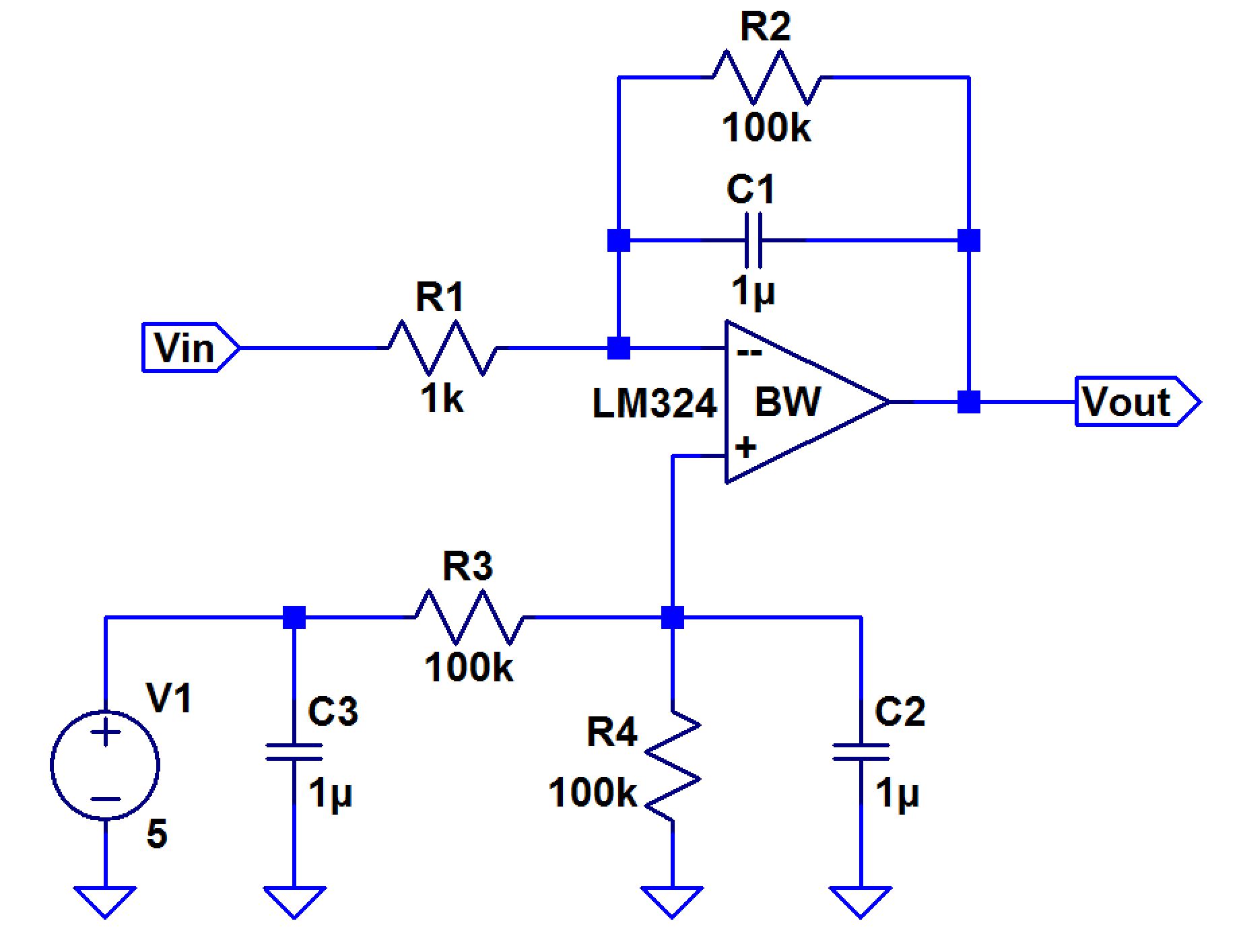
Calculate the frequency response of the following circuit. Ensure you show your clear hand calculations.
Using KCL, the following equations are found to find the magnitude, phase angle, and unity frequency gain of the following circuit below.
| Schematic | Hand-Calculations |
|
-What can you neglect to simplify the calculation?
R2 (100k) can be neglected because it is much bigger compared to R1 causing the value of R1/R2 to be close to 0; therefore, it is negligable.
-Does the circuit work if you remove the 100k? Why or why not?
The circuit would not work if you remove the 100k resistor because the 100k resistor is what creates and compensates for the offset in the simulation. Since the capacitor cannot feed back into the op-amp, the resistor is what feeds back the output voltage of the op-amp into the negative terminal of the op-amp.
-Does the 100k have much of an effect on the frequency response?
The 100k resistor does not have much of an effect on the frequency response because it is too big for the AC current to flow; therefore, it flows through the capacitor since it acts as a short and barely anything flows through 100k resistor.
Verify your calculations with experimental results.

Show, at the unity-gain frequency of the integrator, that the input and the output have the same peak values.
-Is the phase shift between the input and the output what you expect? Why or why not?
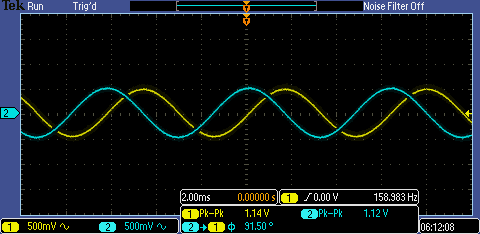
Yes, the phase shift between the input and the output is what I expected because based on the calculations that were made in the beginning, the phase angle was 90 degrees for all frequencies, which was close to the phase angle value in the oscilloscope.
Next, design, simulate, and build a square-wave to triangle wave generation circuit.
-Assume the input/output frequency is 10kHz and the output ramp must swing from 1 to 4 V centered around 2.5V.
-Show all calculations and discuss the trade-offs (capacitor and resistor values, input peak, min, and averages, etc.)
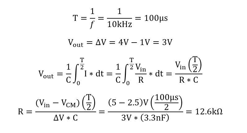
Using nodal analysis, an equation can be derived to help find a resistor and capacitor value for the op-amp integrator circuit. Since the requirements of the circuit design is a frequency of 10kHz and an output ramp that swing from 1 to 4 volts that is centered around 2.5V, the period and differences in voltage can be determined. Once the equation is derived with the known values, a resistor value can be determined based on a capacitor value that available in the lab or vice versa.
Schematic
Hand-Calculations
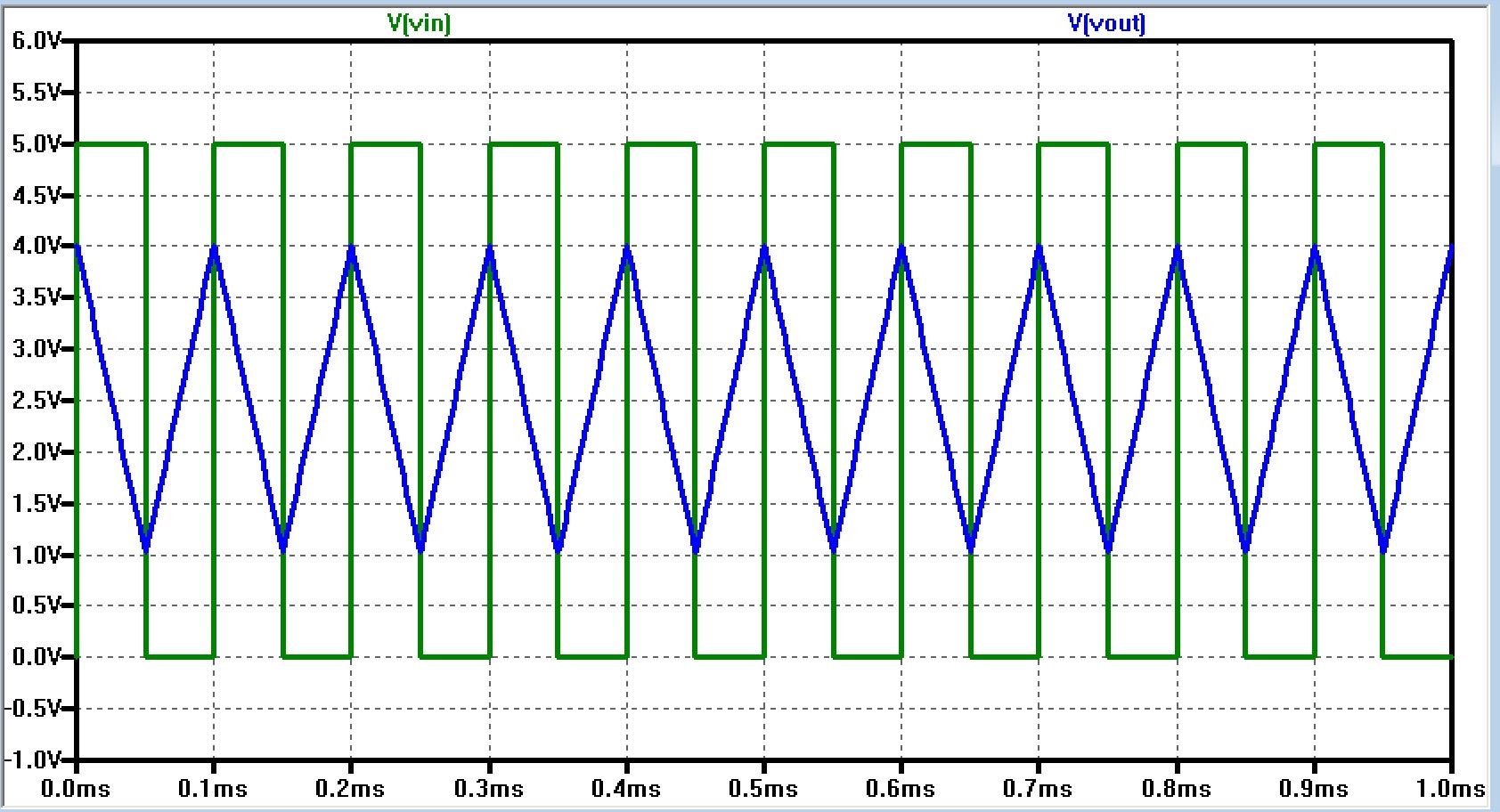
Using the 12.6k resistor for the R1 value and 3.3nF capacitor for the C1 value from the hand-calculations, the LTspice simulated the following results.
Based on the simulation above, all the parameters for the circuit successful met the requirements of this experiment. Next, the same circuit is laid out on a breadboard to be tested out and compared.
Experimental Results

The experimental results are not exactly the same, but close to the LTspice simulation. Since there wasn't any 12.6k resistors, a 12k resistor was used instead, which may have affected the results a bit. Also the probe and oscilloscope capacitance and resistance were not taken in account; therefore, it may have been a factor of the oscilloscope results being slightly different. If the resistor or capacitor value were to decrease, the output ramp swing increases, meaning it would swing below 1V and above 4V; therefore, the other component must be increased to compensate for the output. If the pulse voltage were to change, it would cause the offset voltage to swing at a different value, which cause the output to shift up and down and the amplitude to change in size.