
Lab 4 - EE 420L
Lab Work
Again, this lab will utilize the LM324 op-amp (LM324.pdf).
For the following questions and experiments assume VCC+ = +5V and VCC- = 0V.
Estimate, using the datasheet, the bandwidths for non-inverting op-amp topologies having gains of 1, 5, and 10.
Bandwidth Data
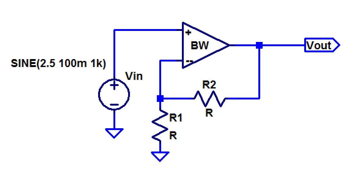
Non-Inverting Circuit
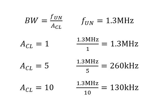
Based on the datasheet, the unity gain frequency of the op-amp is 1.3 MHz and the equation below is the bandwidth equation for a non-inverting op-amp circuit. Depending on the closed loop gain, the estimated bandwidth frequency is found.
Hand-Calculations
Experimentally verify these estimates assuming a common-mode voltage of 2.5V.
-Your report should provide schematics of the topologies you are using for experimental verification along with scope pictures/results.
-Associated comments should include reasons for any differences between your estimates and experimental results.
Circuit

| Gain | 1 |
| Resistor Values | R1 = 100k R2 = wire |
| At 1kHz w/ Vout1 = 208mV |  |
| Vout2 = 144mV (0.7*Vout1) w/ f3dB= 700kHz | 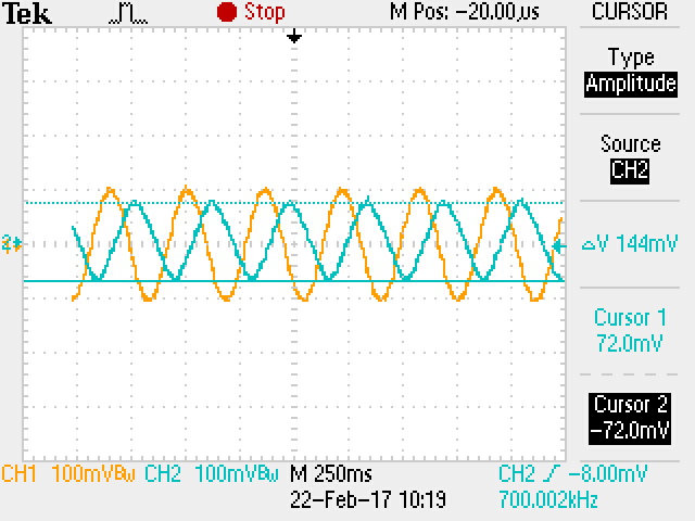 |
| Gain | 5 |
| Resistor Values | R1 = 100k R2 = 400k |
| At 1kHz w/ Vout1 = 452mV | 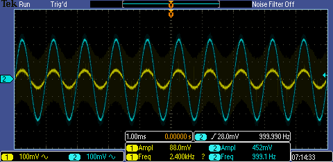 |
| Vout2 = 320mV (0.7*Vout1) w/ f3dB = 110kHz |  |
| Gain | 10 |
| Resistor Values | R1 = 900k R2 = 100k |
| At 1kHz Vout1 = 940mV | 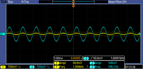 |
| Vout2 = 660mV (0.7*Vout1) w/ f3dB = 40kHz | 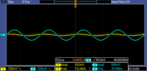 |
The expected values of the 3dB frequency is a lot higher than the experimental 3dB frequency. A few reasons for the huge difference in 3dB frequency is the VCC value and the resistor values used for the gain. The bandwidth frequency value in the datasheet used a VCC value of 30V rather than the 5V used in our experiments. The resistors used in the experiments were more than 100k when the resistor in the datasheet to find the bandwidth frequency is 2k.
Repeat these steps using the inverting op-amp topology having gains of -1, -5, and -10.
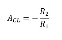
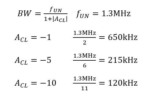
For this experiment, we are using the inverting op-amp topology, so the equations are with respect to the schematic of the circuit below. Resistor values can be chosen based on the closed loop gain equation below and the estimated bandwidth frequency can be calculated using the equations below.
Hand-Calculations and Equations
Circuit

| Gain | -1 |
| Resistor Values | R1 = 100k R2 = 100k |
| At 1kHz, Vout1 = 124mV | 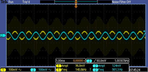 |
| Vout2 = 86mV (0.7*Vout1) w/ f3dB = 620kHz |  |
| Gain | -5 |
| Resistor Values | R1 = 100k R2 = 500k |
| At 1kHz, Vout1 = 480mV | 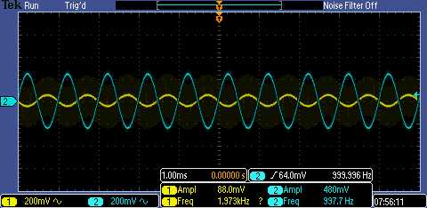 |
| Vout2 = 336mV (0.7*Vout1) w/ f3dB = 80kHz | 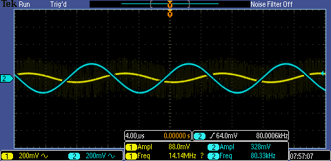 |
| Gain | -10 |
| Resistor Values | R1 = 100k R2 = 1M |
| At 1kHz, Vout1 = 950mV | 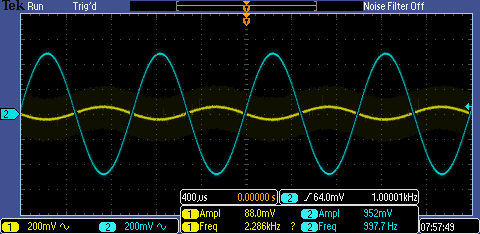 |
| Vout2 = 665mV (0.7*Vout1) w/ f3dB = 37kHz | 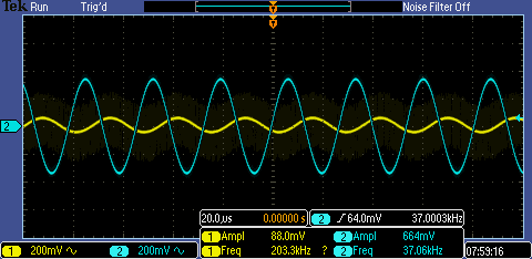 |
As the gain goes higher, the actual 3dB frequency moves further away from the expected 3dB frequency. Again, the reasonings behind are resistors being too high, the VCC being too low, andthe capacitance and resistance in the lab equipments being used.
Design two circuits for measuring the slew-rate of the LM324. One circuit should use a pulse input while the other should use a sinewave input.
-Provide comments to support your design decisions.
Comment on any differences between your measurements and the datasheet's specifications.

Schematic
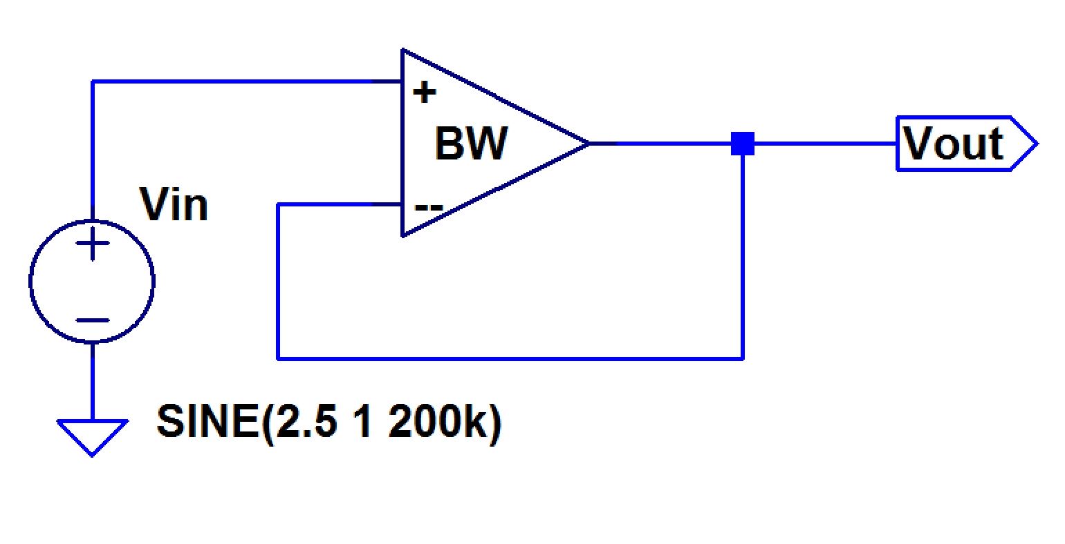
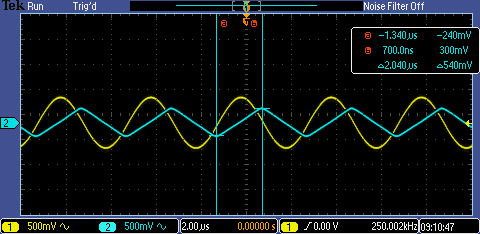
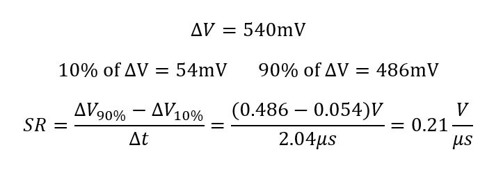
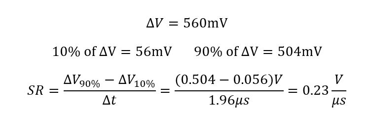
Using the schematic of the unity gain function, we are able to find the slew rate when using a sine wave AC input and a square wave AC input. To find an accurate slew rate, the difference of 90% of the voltage change and 10% of the voltage change are over the difference in rise time.
| Sine Wave Input | Square Wave Input |
 |  |
 |  |