Lab 2 - EE 420L
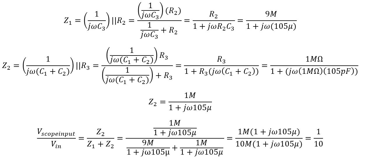
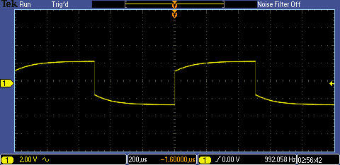
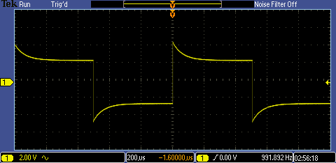
Using the 10:1 probe, connect the probe tip and ground to the side of the oscilloscope and a waveform should be outputted. Based on the waveform, the scope can be adjusted to be undercompensated, overcompensated, and compensated by using the screwdriver to change the capacitance of the probe at the end of the probe.
| Undercompensated | Overcompensated | Compensated |
| | |
Type of Scope Probe
For this lab, a Tetronix scope probe is being used to output the signals on the oscilloscope. It is already set attenuation of 10:1, contains a resistance of 10MΩ, and can have a maximum capacitance of 12pF. Again, the capacitance can be varied by inserting a screwdriver in the hole to adjust it.
LTspice of 10:1 Scope Probe
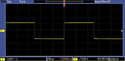
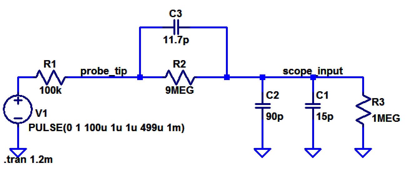
The goal of this experiment is to find a reasonable capacitance value for the probe and scope, so the scope input voltage is 0.1 times the probe tip voltage. The impedances must be found since capacitors and resistors are in parallel with each other. Once the impedances were found, voltage division is used to check if the 1/10 ratio is fulfilled. Once the hand calculations fulfill the requirement, the schematic is created and simulated in LTspice for verification.
Hand-Calculations
Schematic
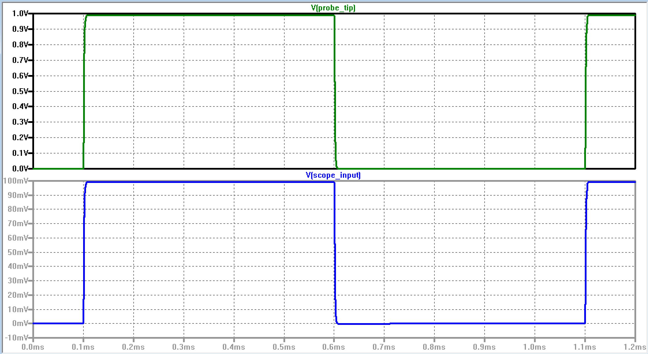
Simulation
Measuring the Probe Capacitance
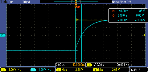
For this experiment, a simple RC circuit is created, where the probe acts as a capacitor and resistor being used is 100kΩ. When output voltage is measured in the oscilloscope, use the cursors to measure the time difference from the time the output voltage is about to rise to the time the ouput voltage has risen to half of the input pulse voltage. The time difference is the time delay, which can be used to determine the probe capacitance.
RC Time Delay
Hand Calculations
Actual Capacitance

Note: The multimeter has a capacitance of about 10.1pF, so the measured capacitance is about 11.4pF, which is about 1pF off from the calculated capacitance value. A factor that may have affected the calculation is the measurements of the RC delay simulation on the oscilloscope and a factor that may have affected the measurement on the multimeter is the set up.
Cable vs. Compensated Probe
To be able to see the difference when measuring the output of a circuit, two 100kΩ resistors are used as a voltage divider and a 0 to 1V pulse with a 1MHz frequency are inputted. As seen in the simulations, the output of the voltage divider is smaller when the probe is uncompensated because the capacitance is large that it takes a while for the capacitor to charge and disharge. For the compensated probe, a capacitance is added with the capacitance and resistance in the scope; therfore, causing the rise time to be shorter and the total resistance to be lower.
| Cable | Compensated Probe |
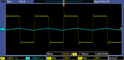 |  |
Test Point on a PCB
Since the length of the cable is known, the capacitance and resistance can be based on the length; therefore, a circuit design that is similar to the probe internally that contains a resistor and capacitor in parallel can be created. Along with the circuit that represents the cable, an additional circuit is added on the PCB depending the attentuation that is wanted to compensate the measurement. Once that is determined, it can be added to the PCB as well to get the proper measurements.