Lab 7 Design of an Audio Amplifier -EE 420L
Authored
by Jeremy Garrod
3/29/2017
garrod@unlv.nevada.edu
Pre-lab work
Lab Work
- Design
an audio amplifier (frequency range from roughly 100 Hz to 20 kHz)
assuming that you can use as many resistors, ZVN3306A transistors, and
ZVP3306A transistors as you need along with only one 10 uF capacitor
and one 100 uF capacitor. Assume that the supply voltage is 10 V, the
input is an audio signal from an MP3 player (and so your amplifier
should have at least a few kiloohms input resistance), and the output
of your design is connected to an 8-ohm speaker (so, ideally, the
output resistance of your amplifier is less than 1 ohm).
To
start the design, the push-pull amplifier that was given in the Lab 7
instructions was simulated. It can be seen below that the input
resistance varies a bit, but starts to level off around 7.7k Ohms. The
output resistance is steady at 8 Ohms, which is the same value of the
load. While the circuit does amplify, it does not amplify very much and
also has a large output resistance.


In
order to have a low output resistance as well as a decent amount of
gain, a common-drain amplifier will be cascaded with the output of the
push-pull amplifier. Common-drain amplifiers typically have a low gain
and a low output resistance, which is suitable for our needs here. In
order to get the best design possible, simulations were done while
varying different parameters.
To
start off, I just used the push-pull amplifier that was given to us and
attached a common-drain amplifier to it. I put the speaker resistance
in parallel with another resistor, but had the 100u capacitor between
the source of the NMOS and the speaker to ensure that only the AC was
able to get through. I then varied that parallel resistance to see what
would happen to the gain as it got larger. I ended up settling on 5
Ohms, since it gave a decent gain but was also low enough to reduce the
output resistance to a more desirable level.


Now
that I had a good idea of what parallel resistor I wanted to use, I
kept that constant while varying the feedback resistor in the push-pull
amplifier. It can be seen below that somewhere betweeen 15k and 20k is
where the output signal starts to get a little bit distorted. I chose
to go with 17k, since it is close to the middle of those two. I figured
there would be minimal distortion on the output while giving as much
gain as possible.


Next,
it was time to put in all my numbers and simulate the final design.
There is no distortion, a decent gain, and fairly low output
resistance. In order to verify that the 5 Ohm parallel resistor, the
current through the common-drain NMOS was analyzed, which confirmed the
initial finding. The output resistance was lowered to around 3 Ohms and
the input resistance was raised up to 10k. This is clearly an
improvement from the amplifier that was given in the lab instructions.
If the resistance is lowered much more, there would be too much power
for the circuit to handle due to the increase in current.
A
2 Ohm resistance was actually used in experimentation as well to test
if the circuit could handle the current, which ended up in the
transistor quickly dying.


Amplifier Output Resistance
Input Resistance


- Building and Experimentation
I
had a lot of difficulty with this portion of the lab. When I had
initailly built the circuit, it worked perfectly. I wanted to try out a
2 Ohm parallel resistance to see if the circuit could handle it, which
killed my common-drain transistor. I grabbed a new NMOS and a
new parallel resistance since mine was pretty far off from the
listed value. When I hooked the circuit back up, nothing would work. My
gain was all over the place, there was a lot of noise on the
oscilloscope, and I couln't get any sound to play through the speaker
we had in the lab. After rebuilding the circuit multple times, I
finally got a waveform, but the gain was very far off. It worked and
played sound, but I could not get an accurate measurement on the
oscilloscope.
Original Oscilloscope output
Current draw of circuit


While
not perfect, the circuit had a sine wave at the output within close
proximity to the simulated gain. One of the measurements was measuring
the wrong channel, so measurement of the input voltage has to be based
on observation of the wave. The current draw was also what was expected.
Second attempt at circuit

I
was not able to figure out the cause of this noise. There were
decoupling capacitors from the power supply and I played around with
every setting I could on the scope to try to filter out some of the
noise. None of that worked. The input noise only occured when the power
supply was turned on.
Third attempt at circuit

I
rebuilt the circuit from scratch after not being able to find the cause
of the issue with the previous circuit. While I was getting an output
that resembled a sine wave, my input wave was had a weird shape and the
output was 13v, which didn't really make a lot of sense to me. However,
very distorted sound did play through the speaker with close to the
same volume as my first attempt.
I was not able to measure any of the required parameters since I could not get the circuit to function properly. I
decided to try another amplifier design as a last ditch effort, since I
could not get my original idea to work in the lab. I wanted a circuit
that could produce clear and loud sound, even if the input and output
resistances were not ideal. I used the push-pull amplifier that was
given to us in the lab instructions, and just increased the feedback
resistor until the gain was high enough and the output wave resembled a
sine wave. I ended up using a 50k resistor in the feedback. The input
resistance leveled off at about 25k and the output resistance was 8
Ohms, the same as the load. The gain was very large, with an output
voltage of about 1.2v.
Design

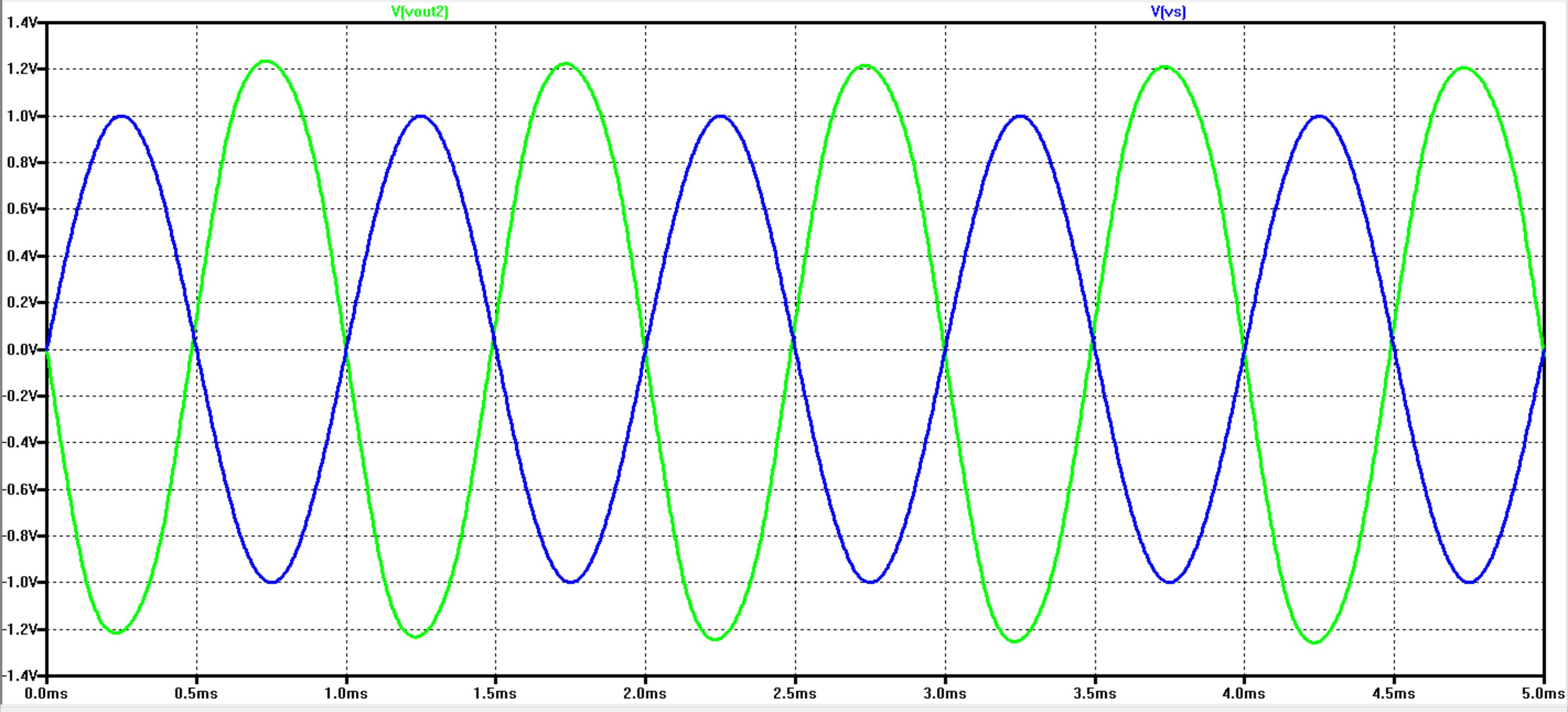


Experiment
Using the above the schematic, I was able to get a gain in the lab that was very close to the gain in the simulations.

I
did not measure the swing or resistances, since this design was only to
obtain a large enough output to drive the speaker. I did not want to do
this design and only made it as a last ditch effort in order to have
something work.
My
simulations worked out exactly as intended. My design met all of the
required design criteria given. When trying to build this circuit in
the lab, everything started to fall apart. I was not able to get good
measurements or even have my original design be functional.
Return to EE 420 Labs