Lab 5 - EE 420L
Authored
by Tyler Ferreira,
ferret1@unlv.nevada.edu
March 2, 2017
Pre-lab work
Again, this lab will utilize the LM324 op-amp (LM324.pdf).
For the following questions and experiments assume VCC+ = +5V and VCC- = 0V.

- Calculate the frequency response of the circuit. Ensure you show your clear hand calculations.

- What can you neglect to simplify the calculation?
I
can neglect the 100k resistor because the R1/R2 ratio is much less than
1. This means R2 makes a negligible difference in our equation.


- Does the circuit work if you remove the 100k? Why or why not?
The
circuit will not work if I remove the 100k resistor. The 100k resistor
is the only feedback path for DC current, without it the output voltage will
go to the power rails (+5V and 0V) with a small
difference between Vp and Vm. This is because of the high open loop
gain of the op-amp.

Looking at the datasheet the LM324 has a
typical open loop gain of 100V/mV or 100kV/V. Using Vout = Aol(Vp-Vm)
we can see that a small
difference between Vp and Vm will cause the output voltage to go
to the positive or negative power rails (+5V or 0V).
- Does the 100k have much of an effect on the frequency response?
The
100k resistor does not have much of an effect on the frequency response
because most of the AC current will flow through the capacitor
rather than the resistor. This is because the
impedance of the capacitor is much less than the resistance of R2.- Verify your calculations with experimental results.

- Show, at the unity-gain frequency of the integrator, that the input and the output have the same peak values.
Hand Calculations for unity-gain frequency

- Is the phase shift between the input and the output what you expect? Why or why not?
I calculated my phase shift to be 90 degrees between my input and output.
In my experiments my signals have
about a 90 degree phase difference between them.
My experimental phase shift is close to what I expected.
- Next, design, simulate, and build a square-wave to triangle wave generation circuit.
- Assume the input/output frequency is 10 kHz and the output ramp must swing from 1 to 4 V centered around 2.5 V.
- Show all calculations and discuss the trade-offs (capacitor and resistor values, input peak, min, and average, etc.)

I decided to choose my resistor value and calculate my capacitor value. I chose a 10k resistor.

In
my integrator circuit I should choose a 4.16nF capacitor and a 10k
resistor. The closest capacitor I could find was a 4nF capacitor and I
was able to get a 10k resistor.
| Schematic | LTspice Simulation | Experimental |
 | 
| 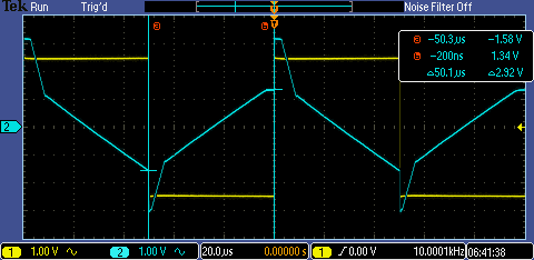 |
Design Considerations:
Capacitor
value: I obtained this value by calculations. I would calculated what I
needed and tried to find a capacitor of similar size in the lab.
Resistor
value: I tried to choose a resistor value of 1k in order to keep the
R1/R2 value negligible in my frequency response. In order to use a 1k
resistor I would need a 41.6nF capacitor which I couldn't get in the
lab. I decided to divide the capacitor value by 10 and multiply the
resistor value by 10 to obtain my current values.
Input
peak/min: I chose a peak of 5V and min of 0V. I chose these values
because I was aiming to get a triangle wave from 1V to 4V. My input min
needed to be at most 1V and my peak needed to be at least 4V. Choosing
0V and 5V made the math easier since the average was centered at my
common mode voltage.
Input average: I wanted the average of my input to be equal to Vcm so there is little to no offset voltage.
I will backup my work on to my OneDrive and my desktop:


Return to the directory listing of my labs
Return to the directory listing of students in EE 420L, Spring 2017
Return to the EE 420L, Spring 2017 webpage