Lab 2 - EE 420L
Authored
by Tyler Ferreira,
ferret1@unlv.nevada.edu
January 31, 2017
Pre-lab work
- Watch the video scope_probe and review scope_probe.pdf (associated notes).
- Vary the parameters in the simulations found in probe.zip to ensure you understand the operation of a compensated 10:1 scope probe.
- From lab 1 ensure that you understand the operation and analysis of simple RC circuits (likely a quiz on this).
- Ensure that you can read/create Bode plots and plot the corresponding signals in the time-domain at a particular frequency.
- Read the write-up seen below before coming to lab
Experiment 1: Show scope waveforms of a 10:1 probe undercompensated, overcompensated, and compensated correctly.
| 10:1 Overcompensated Probe | 10:1 Undercompensated Probe | 10:1 Correctly Compensated Probe |
 |  |  |
Experiment
2: Comment on where the type of scope probe (i.e, 1:1, 10:1, 100:1,
etc.) is set on your scope (some scopes detect the type of probe used
automatically).
The
type of scope probe is set under the channel menu. If you open up the
channel menu on the scope there will be an option to change the compensation of the probe.
Experiment
3: Draft the schematic of a 10:1 scope probe showing: the 9MEG
resistor, 1MEG scope input resistance, capacitance of the cable, scope
input capacitance, and capacitance in the probe tip.
Schematic

Experiment
4: Using circuit analysis, and reasonable/correct values for the
capacitances, show using circuit analysis and algebra (no
approximations), that the voltage on the input of the scope probe is
0.1 the voltage on the tip.
Hand Calculations

Experiment 5: Devise
an experiment, using a scope, pulse generator, and a resistor, to
measure the capacitance of a length of cable. Compare your measurement
results to the value you obtain with a capacitance meter. Make sure you
show your hand calculations.
Experiment:
- Using a known resistor value connect the resistor in series with the scope probe.
- Connect the function generator input to the resistor with the ground connected to the ground of the probe.
- Use the function generator to output a step voltage.
- Use the oscilloscope to measure the time delay of the output voltage at 50% of the input voltage.
- Find the capacitance by using the equation: time delay = 0.7*R*C
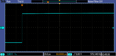
Image of the oscilloscope with the time delay

I measured a time delay of 744ns. Using the equation (td)/(0.7*R) = C I can find the capacitance of the cable.
(744ns)/(0.7*100k) = 10.6pF
Using a multimeter to confirm my calculations
| Capacitance of the cables | Capacitance of (cables + probe) |

|  |
The
capacitance I calculated by doing my RC time delay experiment is off by
1pF compared to directly measuring the capacitance of the probe.
Experiment 6: Build a voltage divider using two 100k resistors. Apply a 0 to 1V pulse at 1 MHz to the
divider's input. Measure, and show in your report, the output of the
divider when probing with a cable (having length greater than or equal
to 3 ft) and then a compensated scope probe. Discuss and explain the
differences.
| Uncompensated Cable | 10x Compensated Cable |
 | 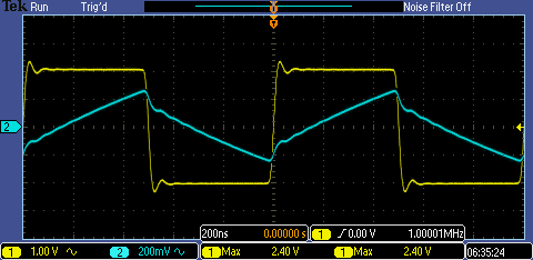 |
Channel 1 (Yellow): Input signal
Channel 2 (Blue): Output signal
Measuring the output voltage with the uncompensated probe results in a larger time delay and higher voltage.
By
using the 10x compensated probe my voltage will be 0.1 times the input
voltage and the time delay will be lower due to less capacitance.
Experiment
7: Finally, briefly discuss how you would implement a test point on a
printed circuit board so that a known length of cable could be
connected directly to the board and not load the circuitry on the board.
To
implement a test point on a PCB we could design the circuit to include
a capacitor and resistor in parallel at this point. By having a
resistor in parallel with a capacitor at the test point it will turn
the uncompensated probe into a compenstaed probe, therefore allowing
the cable to connect directly to the board without loading the
circuitry.
I will backup all of my work on to my OneDrive and my Desktop.


Return to the directory listing of my labs
Return to the directory listing of students in EE 420L, Spring 2017
Return to the EE 420L, Spring 2017 webpage