In this lab we are designing a Beta-Multiplier using the CD4007 chip.
We will be using the level 1 MOSFET model created from
Lab8
to generate our simulated data. The goal of this lab is to design
a BMR that can generate current mirrors with any additional transistor.
- Build your BMR
design and characterize it as you did in the pre-lab
To measure the designed BMR a 1k
resistor was used to measure the current. We want to compare the BMR's
current flow from the left side drain and right side drain to see if
the current has been properly mirrored.
| VDD | Left Side Current | Right Side Current |
| 1V | 0 | 0 |
| 2V | 102.4 uA | 93.6 uA |
| 3V | 500 uA | 477 uA |
| 4V | 1 mA | 970 uA |
| 5V | 1.5 mA | 1.53 mA |
| 6V | 1.9 mA | 2.1 mA |
| 7V | 2.25 mA | 2.7 mA |
| 8V | 2.6 mA | 3.4 mA |
| 9V | 2.9 mA | 4 mA |
| 10V | 3.2 mA | 4.7 mA |
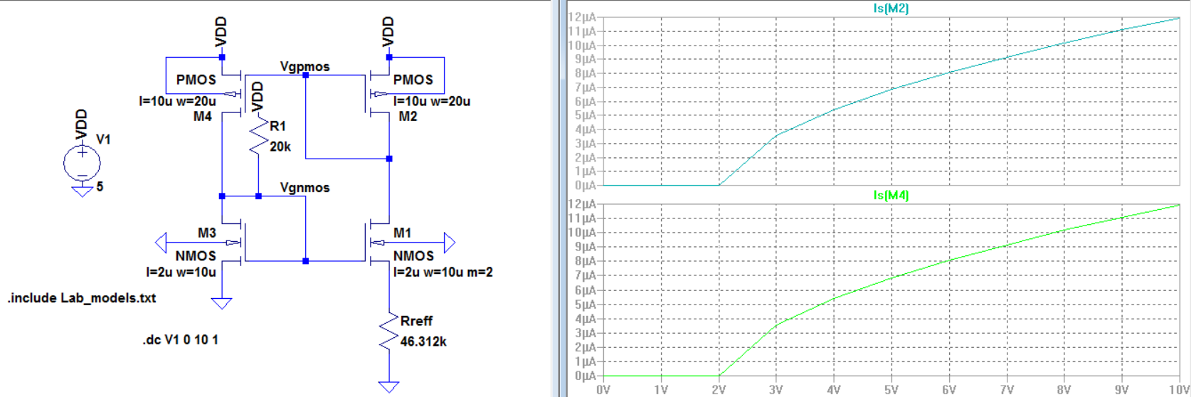
From the simulation data we see that we should have expected a current
range between 0 A to 12uA. We see that for VDD at 1V and below we get
no current flow, both the measured data and simulated data match in
this case, however for higher VDD values the measurements are
incredibly off. This can be due to how the 1k resistor was used to
measure the current, there is a high chance that the resistor may have
effected the DC biasing which will give us wrong values for the
current. Another issue we see here is that with the measured data for
VDD values 7V and above the circuit no longer functions as a current
mirror. Meaning that the physical design of the circuit can only
operate between 0 V and 6 V without issues.
- You
expect the BMR to become unstable if there is a large capacitance
across the resistor, such as a scope probe (important), so care must be
exercised
To rectify this issue the multimeter was use, the wire probes used in
an multimeter has a capacitance much lower than the capacitance in the
scope probe. Therefore we will decrease our issues with instability.
- Use your BMR to
bias, and thus create, a:
- NMOS
current mirror
- PMOS
current mirror
- Measure how the
current varies through each current mirror as the voltage across the
mirror changes.
- Of
course the current in the NMOS (PMOS) current mirror goes to zero as the
voltage on the drain of the output device moves towards ground (VDD)
| VDD | NMOS current mirror | PMOS current mirror |
| 1V | 0 | 0 |
| 2V | 0.193 uA | 0.285 uA |
| 3V | 0.38 uA | 0.5 uA |
| 4V | 1.29 uA | 0.8 uA |
| 5V | 5.2 uA | 4.1 uA |
| 6V | 11 uA | 14.3 uA |
| 7V | 17.5 uA | 19.6 uA |
| 8V | 34.4 uA | 26.7 uA |
| 9V | 47 uA | 36.2 uA |
| 10V | 64 uA | 42.7 uA |
The current flow through these current mirrors are closer
to what we should expect from the BMR circuit. As everything remains in
the micro amp range. The issue here is that we should expect that the
current mirrors for both the nmos and pmos to be the same, however with
the measurments we see that the pmos current wil very less than the
nmos current over VDD.
- Using these current mirrors drive two gate-drain connected transistors
- For the first experiment use the NMOS current mirror to drive two PMOS gate-drain connected devices.
- Use
the voltages on the gate-drain connection of the two devices to bias a
cascode current mirror (characterize this mirror as before)
- For the second experiment switch, that is, use the PMOS current mirror to drive two NMOS gate-drain connected devices.
- Again, use these two voltages to bias an NMOS cascode current mirror then characterize.
| VDD | PMOS driven cascode | NMOS driven cascode |
| 1V | 0 | 0 |
| 2V | 0.003 uA | 0.003 uA |
| 3V | 0.018 uA | 0.021 uA |
| 4V | 0.36 uA | 0.05 uA |
| 5V | 41.1 uA | 2 uA |
| 6V | 171 uA | 52 uA |
| 7V | 350 uA | 180 uA |
| 8V | 570 uA | 361 uA |
| 9V | 880 uA | 580 uA |
| 10V | 1.2 mA | 830 uA |
From the measured data we see that there is a clear issue when
VDD is above 5V. There is either an issue with how the cascodes where
implemented or with how the measurements where taken.