EE 420L Engineering Electronics II Lab - Project

Authored by Sergio Covarrubias

covars1@unlv.nevada.edu

05/03/2016


Project - 
design a transimpedance amplifier (TIA) using either the ZVN3306A or ZVP3306A (or both) MOSFETs and as many resistors and capacitors as you need with a gain of 30k. You should try to get as fast a design as possible driving a 10k load with as large of output swing as possible. AC coupling input and output is okay as long as your design can pass a 100 Hz input current. Your report, in html, should detail your design considerations, and measured resultsshowing the TIA's performance. Your report is due at the end of lab on Wednesday, May 4. Access to your CMOSedu.com accounts will be removed at this time.


First Attempt
I started my project with a simple PUSH-PULL amplifier using both ZVN3306A and ZVP3306A with can acomplish great amouts of gain and good swing as I needed to acomplish a 30K gain which would drive a 10,000 Ohm load.
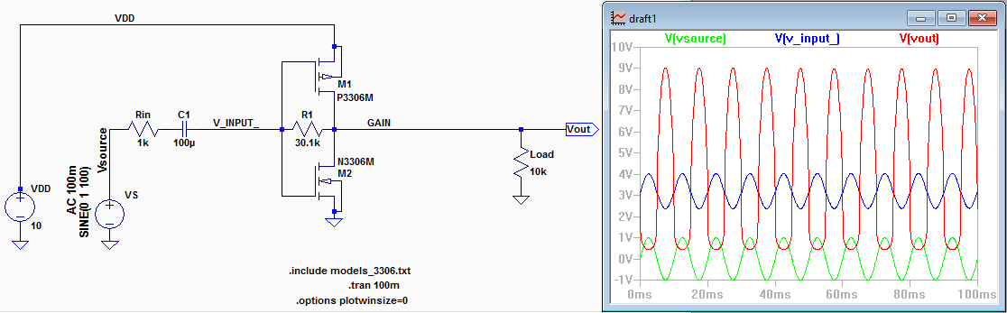
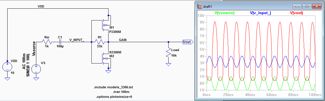
The first thing I did was to work on the LTspice simmulation showed on the screen capture bellow.

pp8swing
ppgain
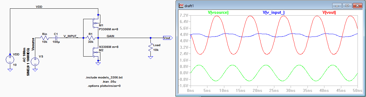
At first I started with PUSH-PULL with only 1 Nmos and 1 Pmos with a 10k Ohm input resitor and a 30K Ohm gain resistor. I noticied that buy adding Nmos and Pmos in parallel it increased the swing voltage by about 0.5V for each set I added. When I got to 8 Nmos and 8 Pmos I had a swing from 2.4v to 7.2v, I also though that I was going to have problems on the BreadBoard in terms of running out of room. The set up shown above I also had a great gain which was not affected by the number of Nmos and Pmos. I was happy with the simmulated results so I went ahead and built the circuit.
8board
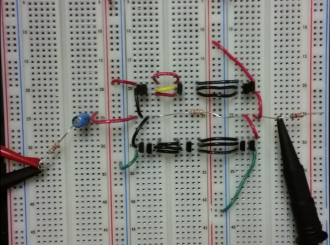
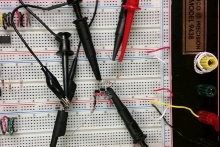
I layed out my circuit the way I had room to add or remove transistors as needed, I also like to make my circuits as simmilar as posible to the LTspice schematic. As soon as I connected my circuit I started having problems with noice and the experimental results did not match the LTspice simmulation at all. I checked my circuit over and over again, I thought I made a mistake when I wired my circuit.
1osi1multi
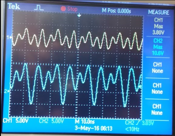
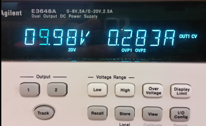
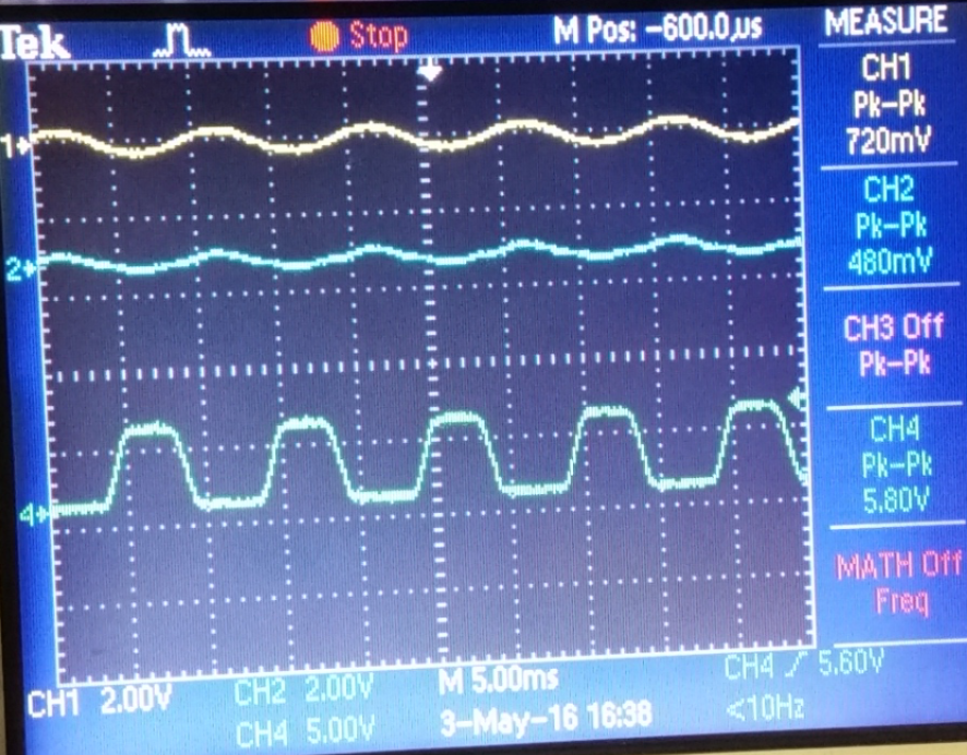
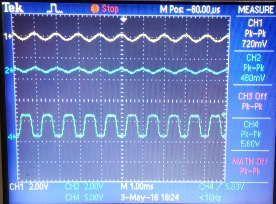
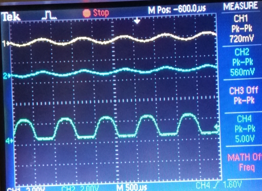
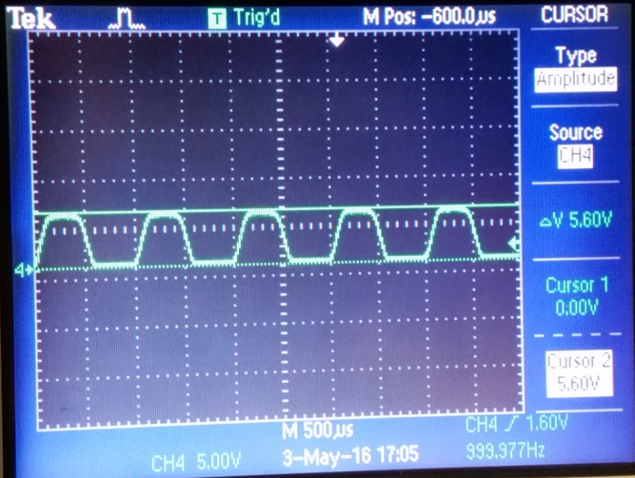
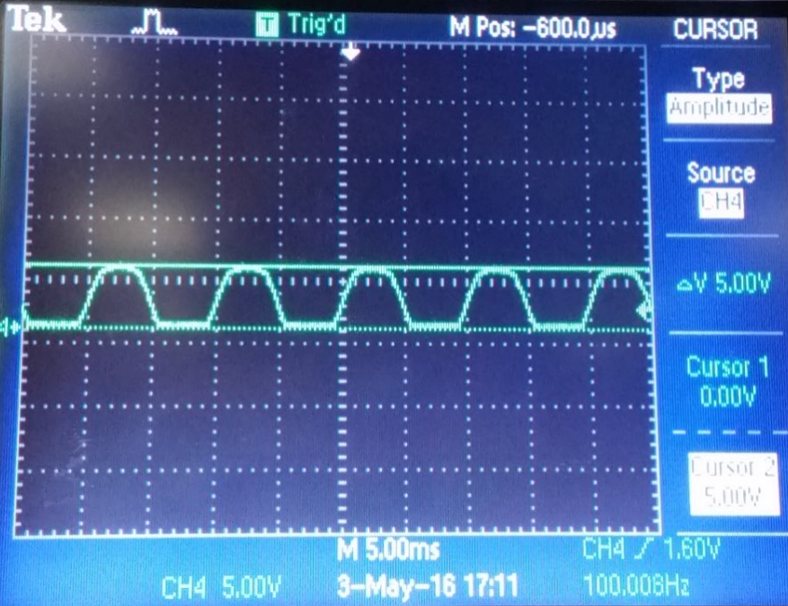
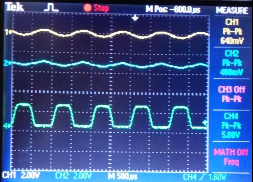
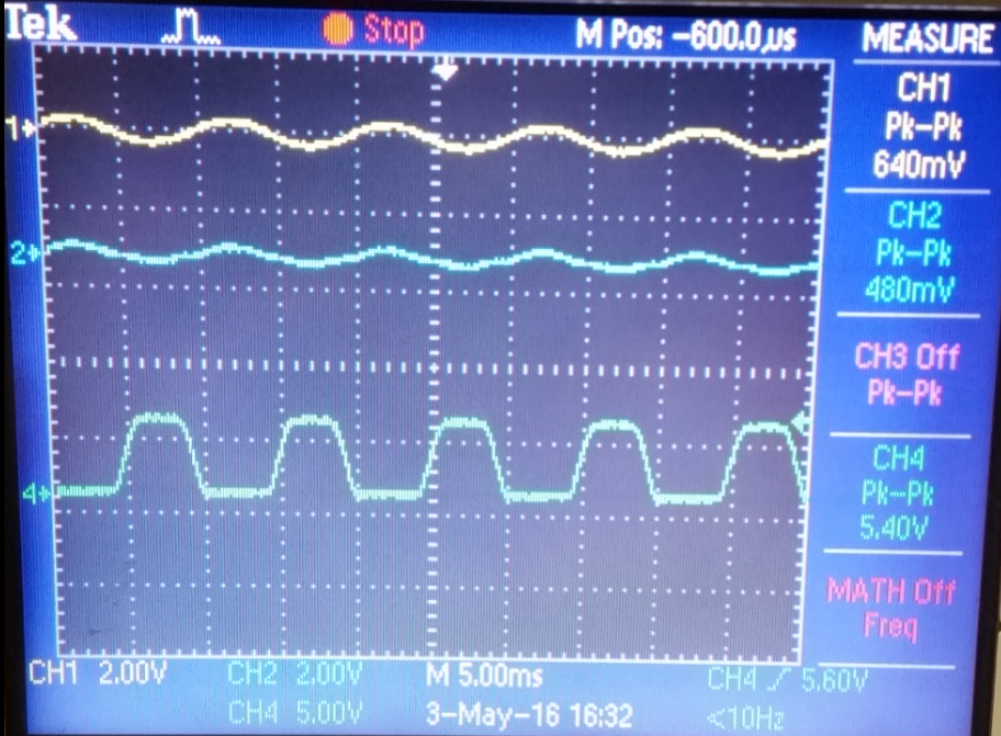
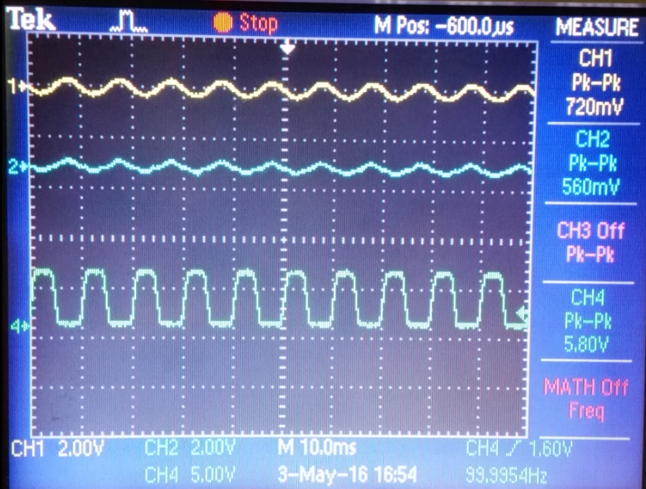
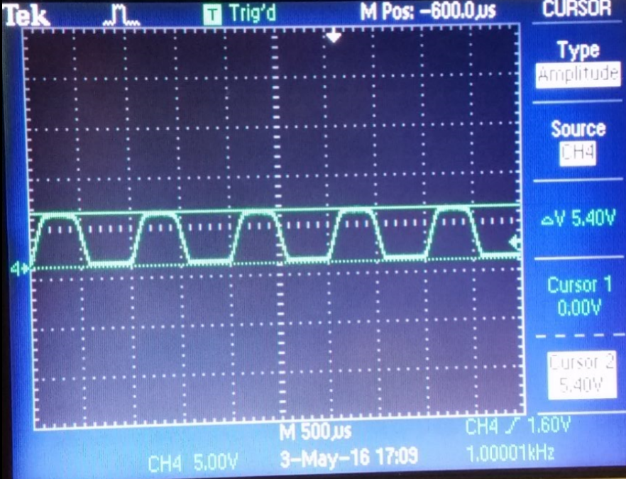
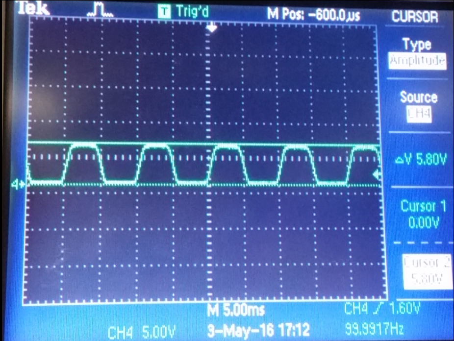
I also had problems with overheating and the current being pulled from the Power Supply was huge. I started by removing Nmos and Pmos one by one which made my current go down but the noice issue did not get better, I noticed that by adding a capacitor on the top main power rails my osciloscope reading would jump around and would actually change drastically. When I went down to only 1 Nmos and 1 Pmos I still had lots of noice which made my input voltage (shown above CH1 yellow) and also on the output swing voltage (shown above on CH4 blue).


Second Attempt
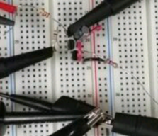
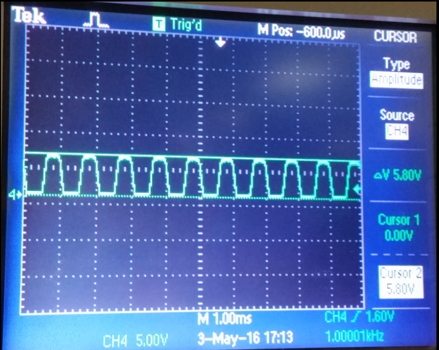
After looking at my circuit for hours and experimenting with different number of Nmos and Pmos in parallel I finally noticed that the noice produced on the "first attempt" circuit was comming from the extended layout with all the jumpers that were necesary to be able to connect multiple Nmos and Pmos in parallel. I started from scratch in as compact as possible design, my new design allowed me to connect only 1 Nmos and 1 Pmos as shown on the screen capture bellow.

gainf 
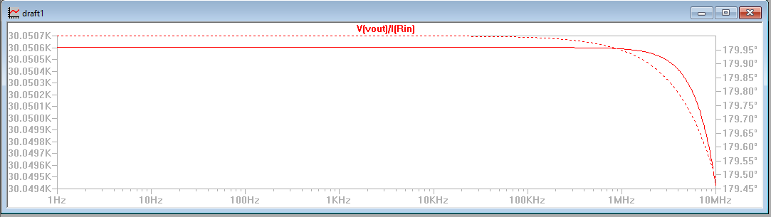
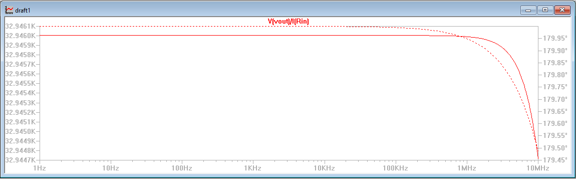
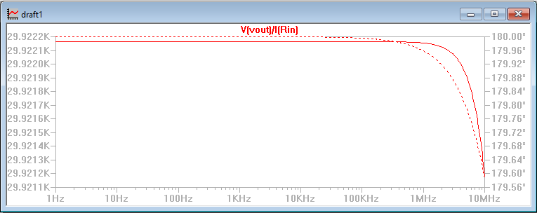
The calculated gain is purelly obtained from the gain resistor in my simulations labeled R1.


boardf

In the LTspice simulations I had a Vout swing from 0.5v to 9.0v getting a 8.5v swing, this is a great swing covering almost all VDD.

30kswing
30.1gain

To accomplish a as close as posible to 30K gain on LTspice I had to use a 30.1K Ohm resistor I also noticed that by using a 1K Ohm input resistor would increase the current to drive the 10K load (I=V/R). I built my "second Attempt" circuit starting by using a 30K Ohm gain resistor.

Using a 30K Ohm gain resistor
CircuitSwing without a load at 1kHz.Swing with load at 1kHz.Swing with load at 100Hz.
board1CH1=720mV
CH2=480mV
CH4=5.80V
2.2
CH1=720mV
CH2=480mV
CH4=5.60V
2.1
CH1=720mV
CH2=5600mV
CH4=5.00V
2.3
5.81k
Swing= 5.8 volts
5.61k
Swing= 5.6 volts
5.0100
Swing= 5.0 volts
Calculations
CH1(yellow)----Vs
CH2(blue)-------VafterRin
CH4(green)------Vout

Gain=(Vout)/((Vs-VafterRin)/(Rin))
Gain=(5.8v)/((0.720v-0.480v)/(1K Ohm))=24.2K
GAIN=24.2K
Calculations

CH1(yellow)----Vs
CH2(blue)-------VafterRin
CH4(green)------Vout

Gain=(Vout)/((Vs-VafterRin)/(Rin))
Gain=(5.6v)/((0.72v-0.48v)/(1K Ohm))=23.33K
GAIN=23.33K
Calculations

CH1(yellow)----Vs
CH2(blue)-------VafterRin
CH4(green)------Vout

Gain=(Vout)/((Vs-VafterRin)/(Rin))
Gain=(5.0v)/((0.72v-0.56v)/(1K Ohm))=31.25K
GAIN=31.25K


Third Attempt
On the "second attempt" circuit I had a great swing with almost 30K gain with and without load which could run on 100Hz and also at very high frequencies. I wanted to be able to produce more that 30K gain so I replaced the 30K Ohm gain resistor and replaced it with a 33K Ohm gain resistor which allowed me to make over 36K gain even driving the load at 1000Hz with would do 33.8K gain and with the load and 100Hz frequency it ran at 36.25K gain. I noticed that when using lower frequencies the gain would slightly increase.

33kswing
33kgain
In the LTspice simulations I had a Vout swing from 0.5v to 9.0v getting a 8.5v swing, this is a great swing covering almost all VDD.

Using A 33K Ohm gain resistor
Circuit-BoardSwing without a load at 1kHz.Swing with load at 1K HZ.Swing with load at 100 HZ.
board1CH1=640mV
CH2=480mV
CH4=5.80V
3.1
CH1=640mV
CH2=480mV
CH4=5.40V
3.2
CH1=720mV
CH2=560mV
CH4=5.80V
3.3
5.81kkkk
Swing= 5.8 volts
5.41k
Swing= 5.4 volts
5.8100
Swing= 5.8 volts

Calculations

CH1(yellow)----Vs
CH2(blue)-------VafterRin
CH4(green)------Vout

Gain=(Vout)/((Vs-VafterRin)/(Rin))
Gain=(5.8v)/((0.64v-0.480v)/(1K Ohm))=36.3K
GAIN=36.3K

Calculations

CH1(yellow)----Vs
CH2(blue)-------VafterRin
CH4(green)------Vout

Gain=(Vout)/((Vs-VafterRin)/(Rin))
Gain=(5.4v)/((0.64v-0.480v)/(1K Ohm))=33.8K
GAIN=33.8K

Calculations

CH1(yellow)----Vs
CH2(blue)-------VafterRin
CH4(green)------Vout

Gain=(Vout)/((Vs-VafterRin)/(Rin))
Gain=(5.8v)/((0.720v-0.56v)/(1K Ohm))=36.2K
GAIN=36.2K

Comparing the LTspice simmulations to the experimental results I had LTspice swing of 8.5v and 5.6v swing on my experimental results, this was not too far off. Also looking at the gain I achived on LTspice 32.9K gain and on my experimental results I had 36.2K gain whitch is also very close. The reason I used a 100uF capacitor insted of a 10uF capacitor was because it was necesary to filter out the generated noice. I also used a 1K Ohm input resistor insted of a smaller one was because the smaller the resistor the greater the current. At one poit I tried using a 300 Ohm resistor but the current would go up and the Nmos and Pmos would start to heat up too much. This project took too much time to complete because I did not know that any extra wiring (jumpers) connecting circuit componects they add capacitance whitch affects the readings on the osciloscope. For the furure I will keep my circuits as compact and as simple as posible to avoid as much error as posible.

Return to COVARS1 Homepage

Return to EE 420L Labs