EE 420L Engineering Electronics II Lab - Lab 7
Design of an audio amplifier
Pre-lab work
Design an audio amplifier (frequency range from roughly 100 Hz to 20 kHz) assuming that you can use as many resistors, ZVN3306A transistors, and ZVP3306A transistors as you need along with only one 10 uF capacitor and one 100 uF capacitor. Assume that the supply voltage is 10 V, the input is an audio signal from an MP3 player (and so your amplifier should have at least a few kiloohms input resistance), and the output of your design is connected to an 8-ohm speaker (so, ideally, the output resistance of your amplifier is less than 1 ohm).
Ensure
that your html lab report includes your name, the date, and your email
address at the beginning of the report (the top of the webpage).
When finished backup your work.
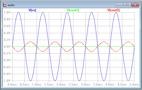
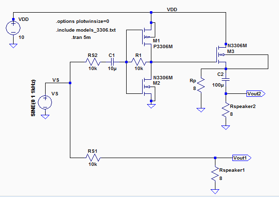
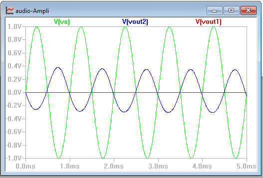
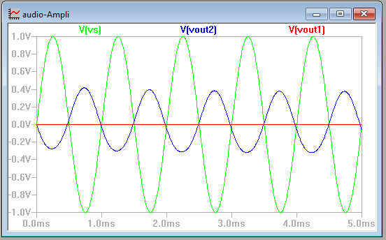
Below is a comparison between driving a speaker without (red, Vout1) and with (black, Vout2) an audio amplifier. The source resistance is 10k meaning that the source can supply 1 V (blue, Vs) at 100 uA maximum. The simulation files used to generate this figure are found in lab7_sims.zip.
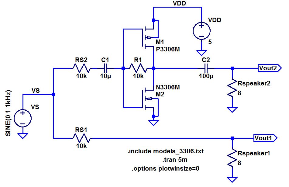
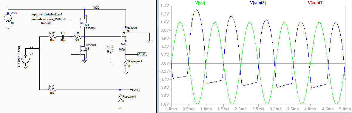
In this experiment I designed an amplifier using a 10v power supply. I started with experimenting and slightly changing the resistors to lean the behavior or the amplifier. The first thing I relised is that as R1 was increased the output would also increased, it would make a big difference on the amplification but anything over 12k ohms we start to see clipping and at 200K ohms we see huge clipping.
I desided to add a Nmos ZVN3306A transistor at the output and a 8 ohm resistor in parallel with the Speaker1.
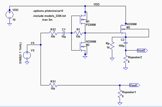
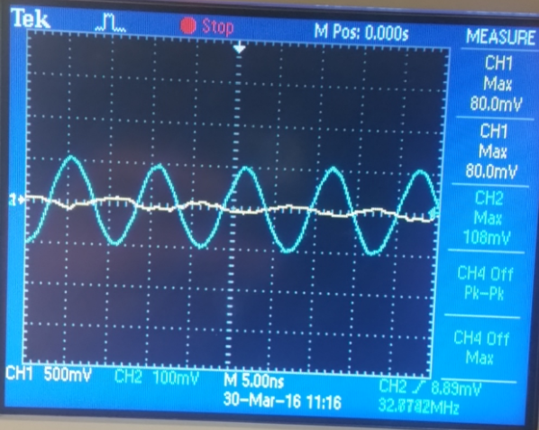
After doing some more examination of the amplifier behavior I noticed using calculations that the lower the output resistance the greather the gain would be and I switched the Rp (which is parallel with the Rspeaker2) the amplification would increase. I switched the Rp resistor to a 4 ohm resistor but the output amplification did not increased at expected. I switched it to a 16 ohm resistor and the amplification improoved slightly. By adding the extra Nmos and the 16 Ohm resistor I was able to improove from bout 0.2V to a little over 0.4V which improoved the output amplification by about 100%.
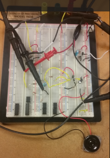
| Screen capture of circuit on bredboard | Screen capture of circuit with added Nmos and the 16 ohm resitor. | Gain-calculations........... |
 |  |
id = Vsg1 * (gm1)
id = Vgs2 * (gm2) Vout/Vin =
(R1)*(gm1 +gm2) |
| Current used by the circuit | Calculations | LTSpice Simulation |
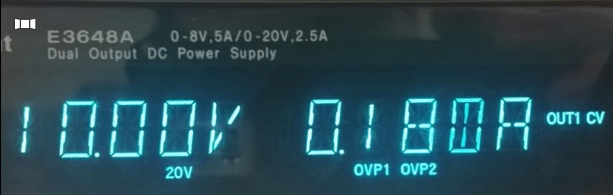 | 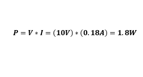 | 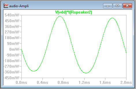 |
For some reason my calculated power consumtion and my LTSpice power simulation did not match, but we can see the the power changes with time and goes up to 0.540 Watts.