EE 420L Engineering Electronics II Lab - Lab 5
Authored by Sergio Covarrubias
covars1@unlv.nevada.edu
03/07/2016
Op-amps III, the op-amp integrator
Pre-lab work
Again, this lab will utilize the LM324 op-amp (LM324.pdf).
For the following questions and experiments assume VCC+ = +5V and VCC- = 0V.
- Calculate the frequency response of the following circuit. Ensure you show your clear hand calculations.
- What can you neglect to simplify the calculation?
- Does the circuit work if you remove the 100k? Why or why not?
- Does the 100k have much of an effect on the frequency response?
- Verify your calculations with experimental results.
- Show, at the unity-gain frequency of the integrator, that the input and the output have the same peak values.
- Is the phase shift between the input and the output what you expect? Why or why not?
- Next, design, simulate, and build a square-wave to triangle wave generation circuit.
- Assume the input/output frequency is 10 kHz and the output ramp must swing from 1 to 4 V centered around 2.5 V.
- Show all calculations and discuss the trade-offs (capacitor and resistor values, input peak, min, and average, etc.)
Ensure
that your html lab report includes your name, the date, and your email
address at the beginning of the report (the top of the webpage).
When finished backup your work.
Part #1 Calculate the Frequency Responce
- What can you neglect to simplify the calculation?
We can simplify our calculation by not including our
Rbig or R2 resistor, the Op-Amp will still be the integration topology.
R2 is only used as the DC feedback channel and we are only usig AC
fequency responce.- Does the circuit work if you remove the 100k? Why or why not?
Removing the R2 100k resistor the DC current will
not have a channel to run on and the capacitor will be like an open
circuit for DC current. Another way of looking at it (no R2 is
R2=infinity) which will make our DC gain infinity and it will not go to
our wanted 0v or 5v. We always want a stable DC gain.
- Does the 100k have much of an effect on the frequency response?
As we said before, the R2 resiter or 100k is only
used for DC feedback and gain. This does not affect the AC analysis.
The triangle wave is generated by the AC current that flows through the
capacitor as it charges and discharges.
| Sine wave at BW=159Hz | Sine wave at BW=159Hz |
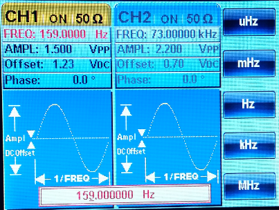 | 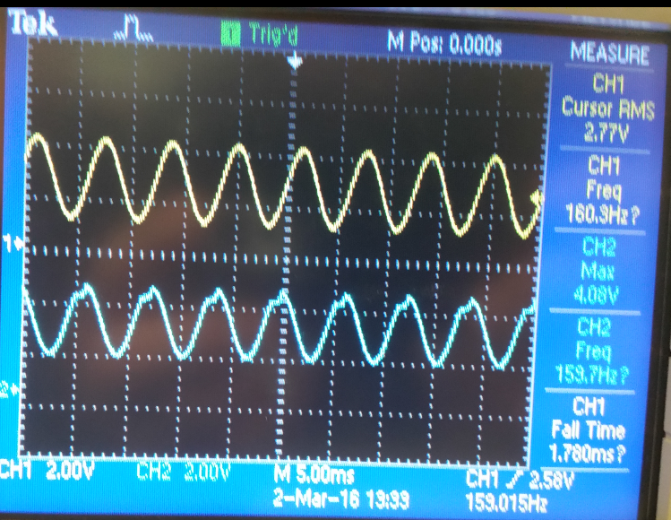 |
Fun = j/2pi*RC
Fun = j/2pi*100k*1u = 159Hz
Part #2 Generating the Triable wave from Square wave input
| Square wave input at 10kHz | Square wave input at 10kHz and triangle wave output |
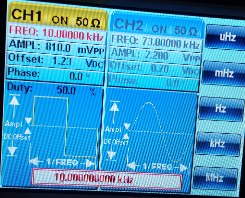 |  |
R=(Vinx0.5T)/(CxdeltaV)
R=(2.5x0.5mS)/(3x2.2nF)= 189394 ohms
T=0.5mS
C=2.2nF
deltaV=3V
| Using the Calculated R=189394 ohms(does not generate the correct 3v swing) | Using 135K resitor that actually gives us the 1-4v swing with 3v change |
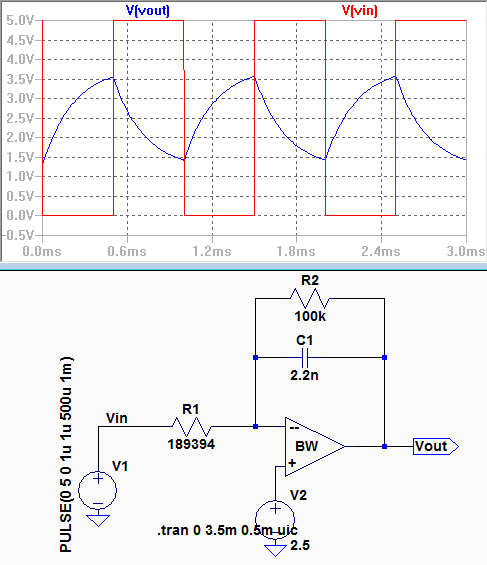 | 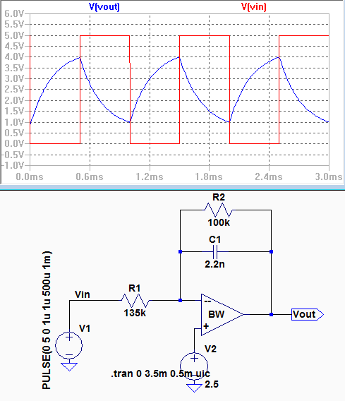 |
On this lab I used the formula R=(Vinx0.5T)/(CxdeltaV)
to find the value of R, using C=2.2nF R came up to be 189394 ohms, I
used a 200K resitor in my circuit and the output was correct, but on my
LTspice simulation I had to use a 135K resitor to be able to get the
correct swing from 1v to 4v which give us the 3V change.
Return to COVARS1 Homepage
Return to EE 420L Labs


