Lab 4 - EE 420L
Authored by Sergio Covarrubias
covars1@unlv.nevada.edu
02/24/2016
Op-amps II, gain-bandwidth product and slewing
Again, this lab will utilize the LM324 op-amp (LM324.pdf).
For the following questions and experiments assume VCC+ = +5V and VCC- = 0V.
- Estimate, using the datasheet, the bandwidths for non-inverting op-amp topologies having gains of 1, 5, and 10.
- Experimentally verify these estimates assuming a common-mode voltage of 2.5 V.
- Your
report should provide schematics of the topologies you are using for
experimental verification along with scope pictures/results.
- Associated comments should include reasons for any differences between your estimates and experimental results.
- Repeat these steps using the inverting op-amp topology having gains of -1, -5, and -10.
- Design
two circuits for measuring the slew-rate of the LM324. One circuit
should use a pulse input while the other should use a sinewave input.
- Provide comments to support your design decisions.
- Comment on any differences between your measurements and the datasheet’s specifications.
Ensure
that your html lab report includes your name, the date, and your email
address at the beginning of the report (the top of the webpage).
When finished backup your work.
Part #1
- Estimate, using the datasheet, the bandwidths for non-inverting op-amp topologies having gains of 1, 5, and 10.

To find the Bandwidth we will use Bw=FUN/Gain
FUN= 1.3MHz
=1.3MHz(1)=1.3MHz
=1.3MHz(5)=260kHz
=1.3MHz(1)=130kHz
| Gain | Banwidth
in HZ |
| 1 | 1.3MEG |
| 5 | 260K |
| 10 | 130K |
Part #2
- Experimentally verify these estimates assuming a common-mode voltage of 2.5 V.
- Your
report should provide schematics of the topologies you are using for
experimental verification along with scope pictures/results.
- Associated comments should include reasons for any differences between your estimates and experimental results.
| Gain of 1 (LTspice circuit) | Experimental Results of Gain 1:
|
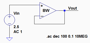
Vin*GAIN*(0.7)=(360mV)(1)(0.7)=252mv=Vout
Which is very close to our OUTPUT of 260mV | 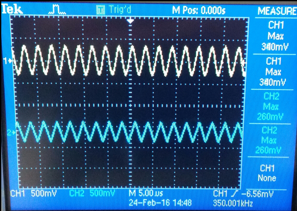
INPUT= 360mV
OUTPUT = 260mv
Which give us a gain of about 1.
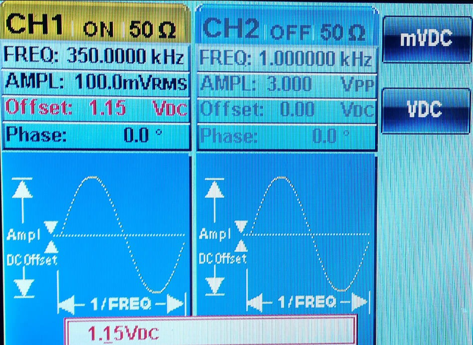
You can also see that our bandwidth frequency 350kHz |
| Gain of 5 (LTspice circuit) | Experimental Results of Gain 5: |
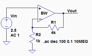
Vin*GAIN*(0.7)=(360mV)(5)(0.7)=1.26v=Vout
Which is very close to our OUTPUT of 1.26v | 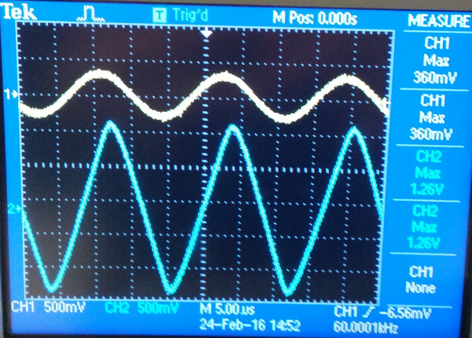
INPUT= 360mV
OUTPUT = 1.26v
Which give us a gain of about 5.
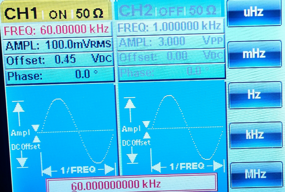
You can also see that our bandwidth frequency 60kHz |
| Gain of 10 (LTspice circuit) | Experimental Results of Gain 10: |
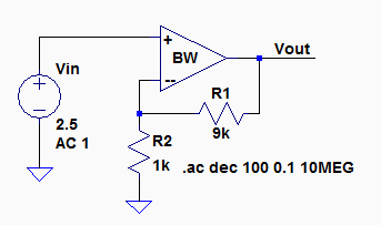
Vin*GAIN*(0.7)=(144mV)(10)(0.7)=1.008v=Vout
Which is very close to our OUTPUT of 1.04V | 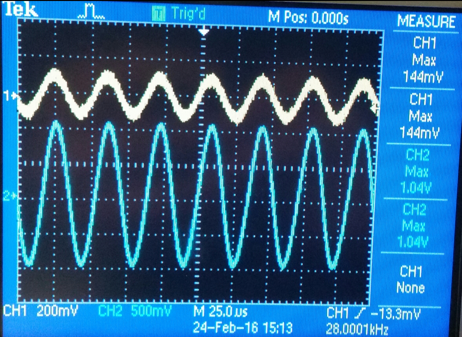
INPUT= 144mV
OUTPUT = 1.04v
Which give us a gain of about 10.
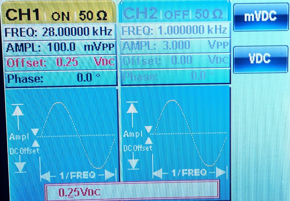 |
Part #3 Repeat these steps using the inverting op-amp topology having gains of -1, -5, and -10.
To find the Bandwidth we will use Bw=FUN/(R1+R2)
FUN= 1.3MHz
=1.3MHz/(1+1)=650kHz
=1.3MHz(1+5)=216.66kHz
=1.3MHz(1+10)=118.1kHz
| Gain | Banwidth
in HZ |
| -1 | 650kHz |
| -5 | 216.66kHz |
| -10 | 118.1kHz |
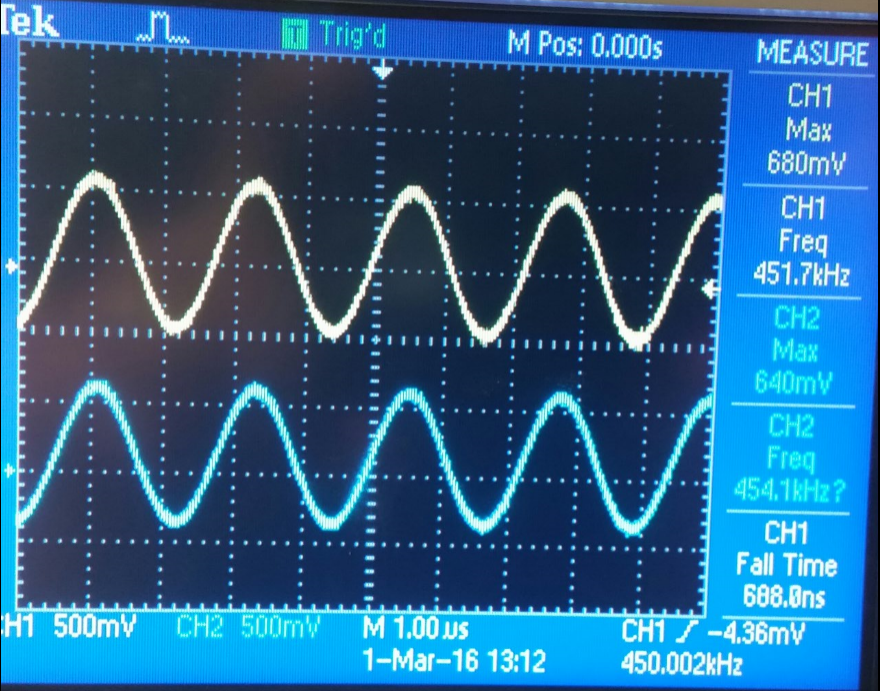
| Gain of -1 (LTspice circuit) | Experimental Results of Gain -1: |
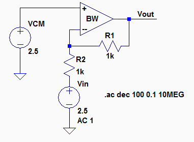 Vin= 680mv Vin= 680mv
Vout=640mv
Bw= 450KHz | 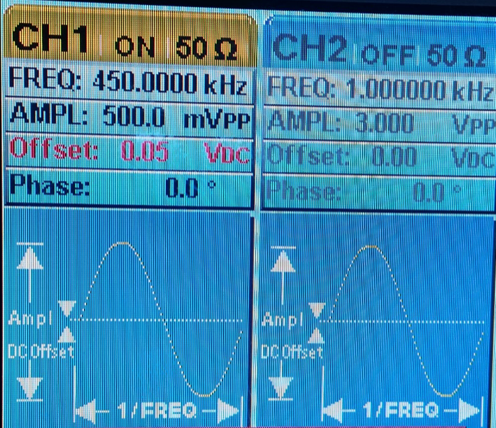
 |
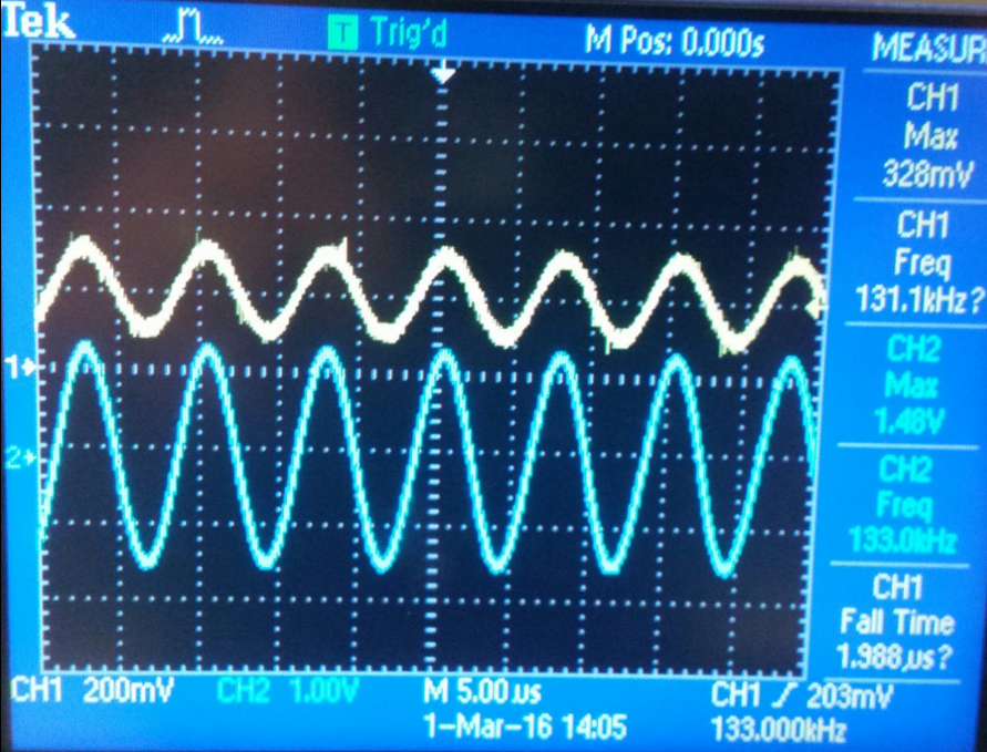
| Gain of -5 (LTspice circuit) | Experimental Results of Gain -5: |
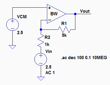
Vin= 328mV
Vout=1.48V
Bw= 133kHz | 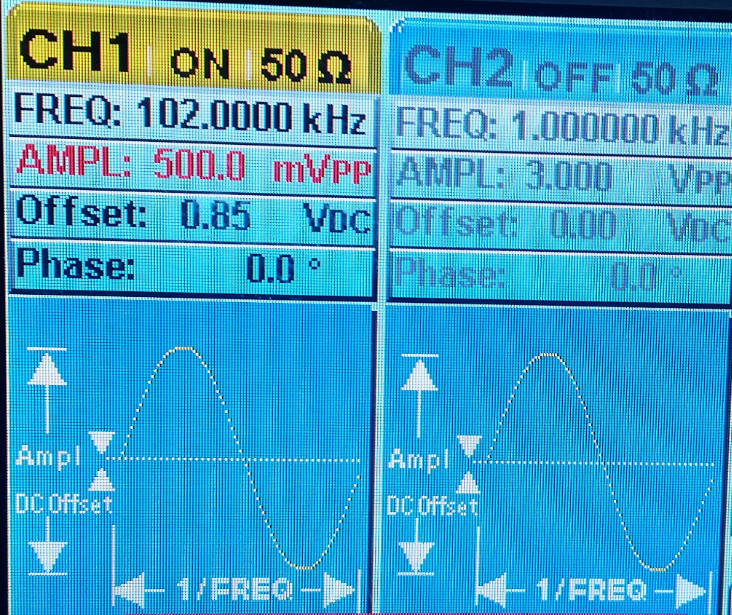
 |
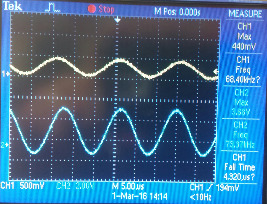
| Gain of -10 (LTspice circuit) | Experimental Results of Gain -10: |
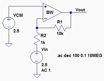
Vin= 440mV
Vout=3.68V
Bw= 68.40kHz | 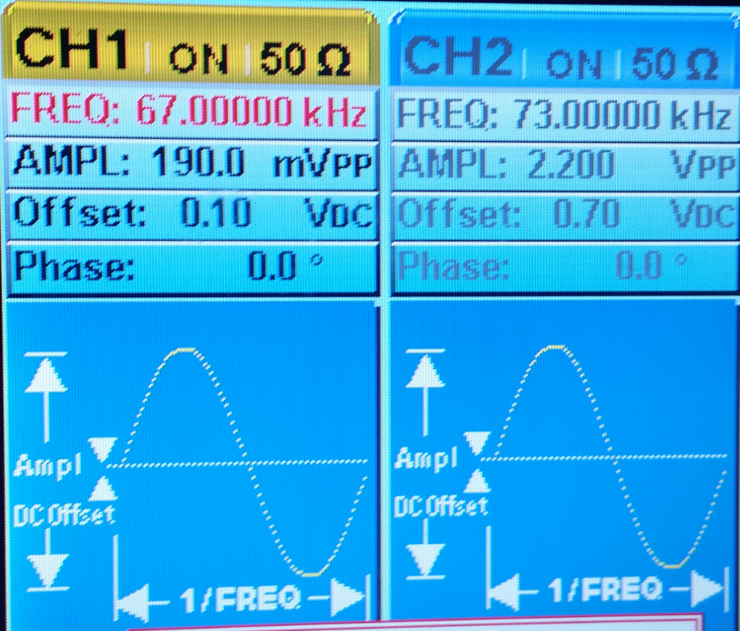
 |
Part #4
- Design
two circuits for measuring the slew-rate of the LM324. One circuit
should use a pulse input while the other should use a sinewave input.
- Provide comments to support your design decisions.
- Comment on any differences between your measurements and the datasheet’s specifications.
| Non-Inverting Op-amp topology | PULSE WAVE INPUT | SINE WAVE INPUT |
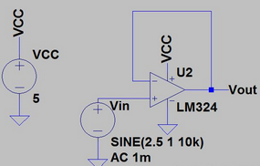 | 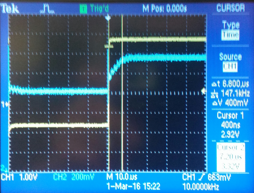 | 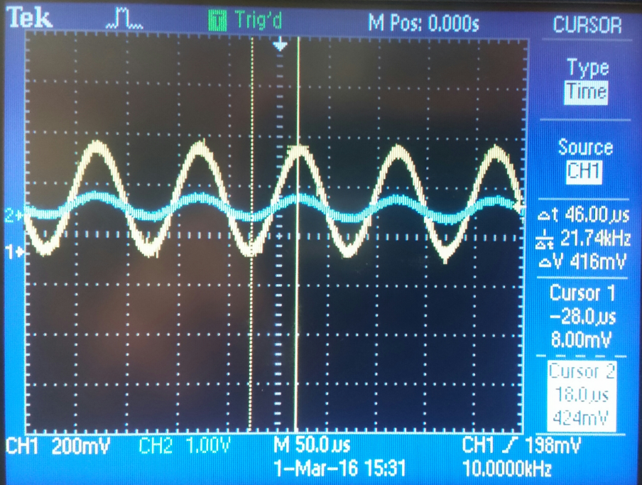 |
SLEW RATE= deltaV/deltaT=2.43V/6.8us=0.357 v/uS compared to the 0.4 v/uS from the data sheet showed bellow.

Return to EE 420L Labs