Lab 2 - EE 420L
Authored by Sergio Covarrubias
covars1@unlv.nevada.edu
02/05/2016
Operation of a compensated scope probe
Perform, and document in your html lab report, the following:
- Show scope waveforms of a 10:1 probe undercompensated, overcompensated, and compensated correctly.
- Comment
on where the type of scope probe (i.e., 1:1, 10:1, 100:1, etc.) is set
on your scope (some scopes detect the type of probe used automatically).
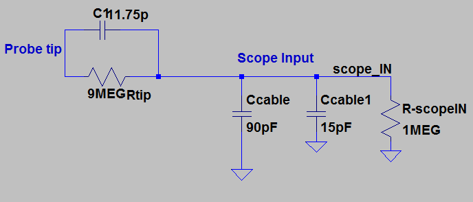
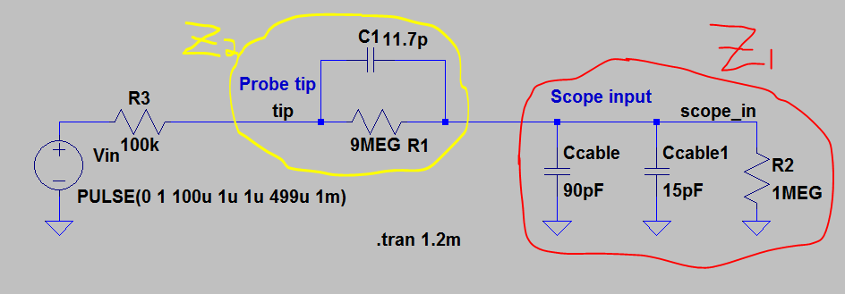
- Draft
the schematic of a 10:1 scope probe showing: the 9 MEG resistor, 1 MEG
scope input resistance, capacitance of the cable, scope input
capacitance, and capacitance in the probe tip.
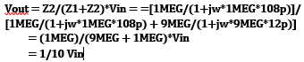
- Using
circuit analysis, and reasonable/correct values for the capacitances,
show using circuit analysis and alegbra (no approximations), that the
voltage on the input of the scope is 0.1 the voltage on the probe tip.
- Devise
an experiment, using a scope, pulse generator, and a resistor, to
measure the capacitance of a length of cable. Compare your measurement
results to the value you obtain with a capacitance meter. Make sure you
show your hand calculations.
- Build
a voltage divider using two 100k resistors. Apply a 0 to 1 V pulse at 1
MHz to the divider's input. Measure, and show in your report, the
output of the divider when probing with a cable (having a length
greater than or equal to 3 ft) and then a compensated scope probe.
Discuss and explain the differences.
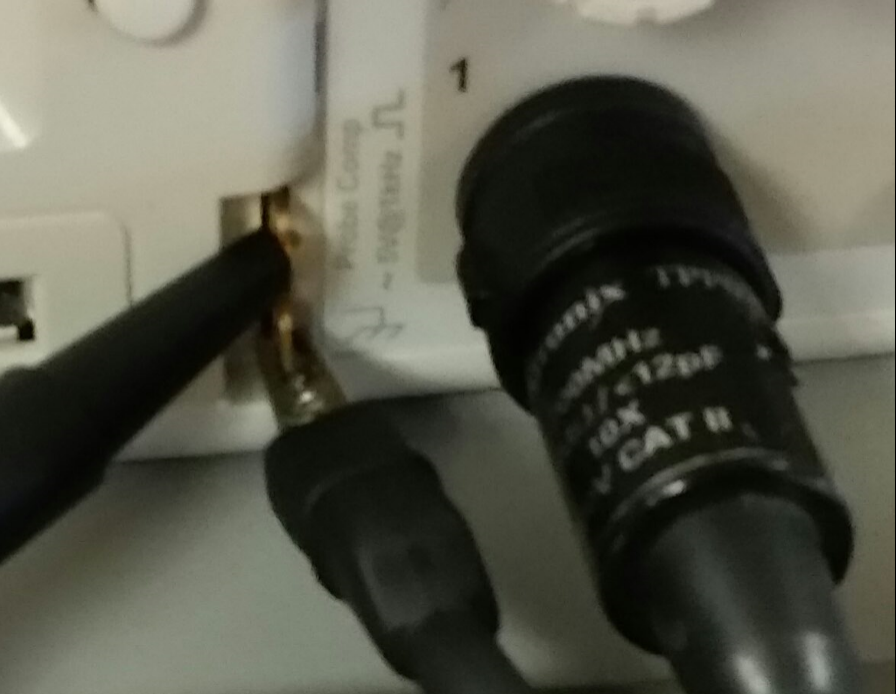
- Finally,
briefly discuss how you would implement a test point on a printed
circuit board so that a known length of cable could be connected
directly to the board and not load the circuitry on the board.
Part #1 (Scope waveforms using a 10:1 scope probe)
| Undercompensated | Compensated | Overcompensated |
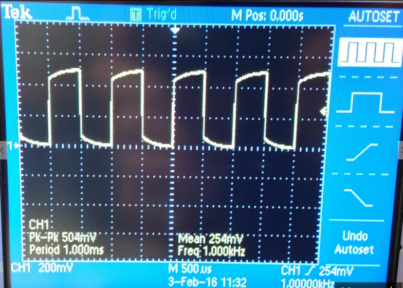 | 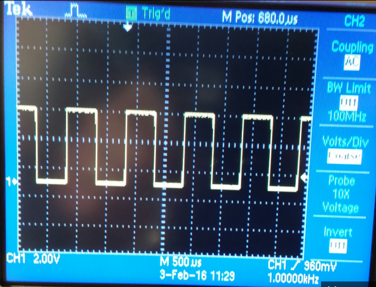 | 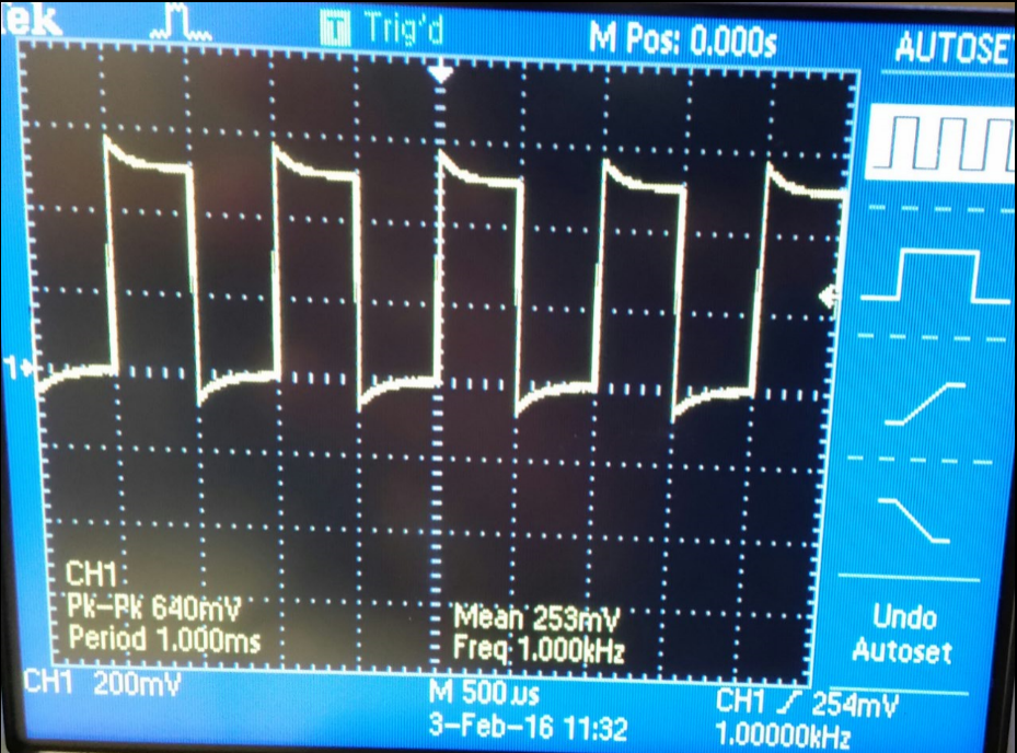 |
Part #2 (I used the regular 10X with no option to switch from 1X to 10X
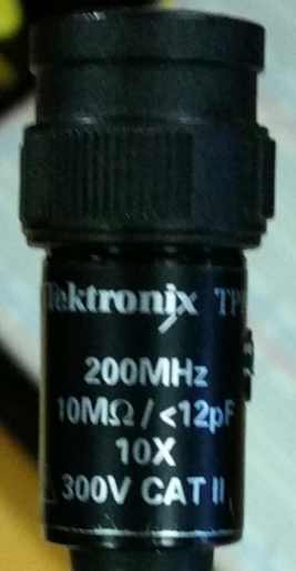
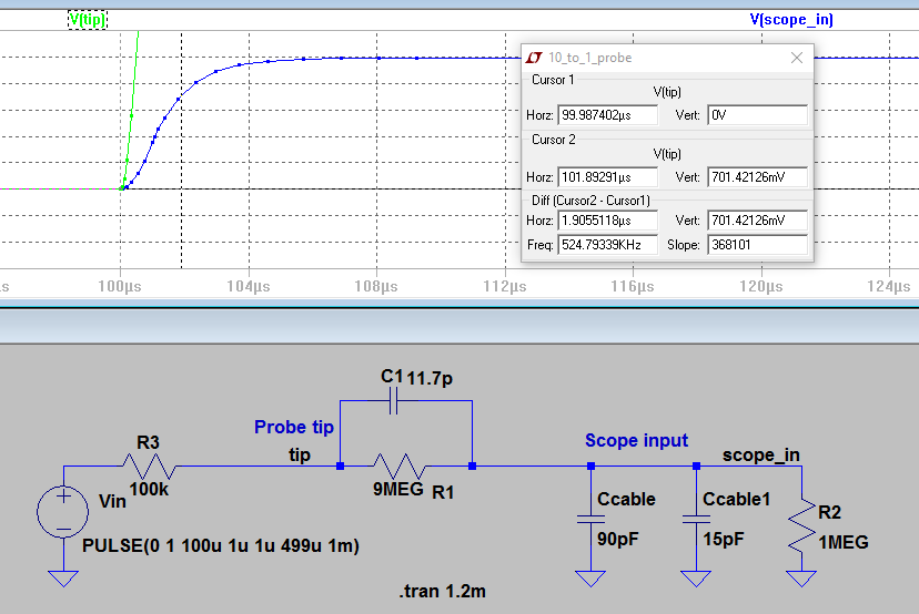
Part #3 (Schematic of the 10:1 probe scope used)
-Using a 1:1 probe 1V input we get a 1V output.
-Using a 10:1 probe 1V input we get a 0.10V output.
-Using a 100:1 probe 1V input we get a 0.01V output.
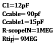
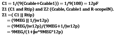
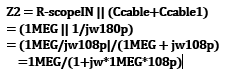
Part #4 (Calculations to find the Vout using the formula and assuming 90pF of cable capacitance.)
| Calculation Values | Finding Z1 | Finding Z2 | Calulating Vout |
| 
|
| 
|
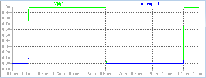
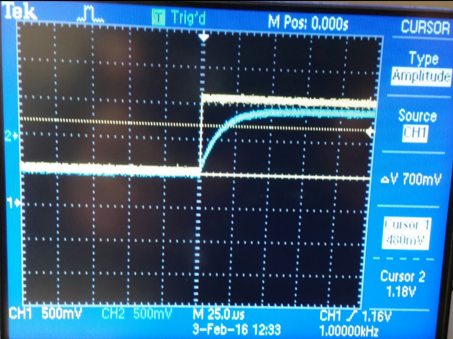
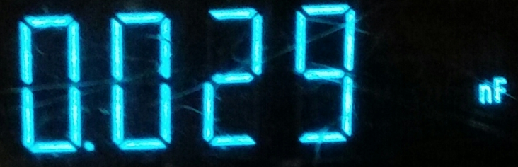
Part #5 (Calculate the capacitance of the scope prove using Oscilloscope data.)
In
this experiment we are measuring the time delay of our circuit, and by
using which allows us to use the time delay formula to calculate the capacitance.
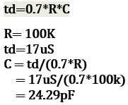
Using the multimeter we get 29pF which is very close to our calculated capacitance.
| V(delta)=700mV | Time(delta)=17uS | Fuction generator at 1kHz | C= 29pF |
 |  |  |  |
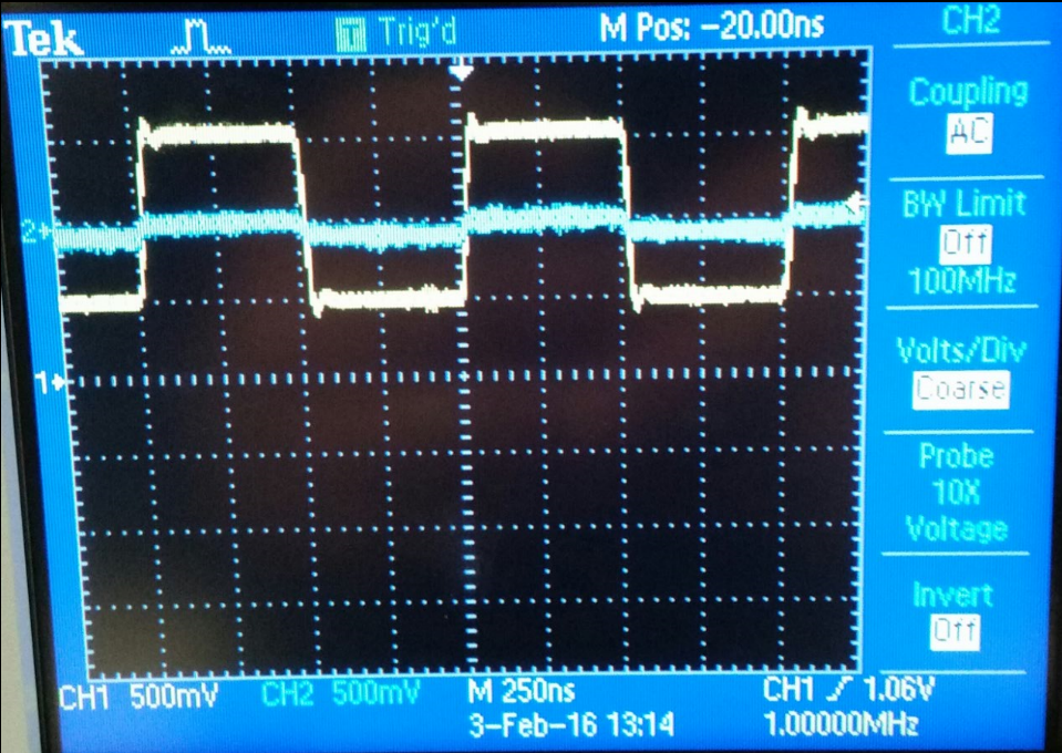
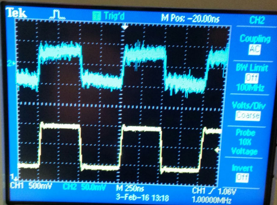
Part #6 (Difference between probing with a cable and a compensated scope probe)
The picture on the right displays the input and output when
probing the output using a compensated probe, the picture on the left
shows the output measured with an uncompensated cable.
A 10:1 scope prove has an output of 100mV and 1V input. A compensated
probe reduces significally the capacitance of the wire making it faster
to charge and also increasing the speed in which signals can be
transmited and measured. On the other hand using just a cable
(unconpensated scope probe) the capacitance is big which makes it very
difficult for the signals to go across it.
| Probing with a cable | Probing with a compensated scope probe |
 |  |
Part #7 (Briefly discuss how you would implement a test point on a printed circuit board)
A
good way to implement a test point on a printed circuit board would be
adding a resistor and a capacitor in parallel before connecting the
cables, by doing this using the right size resistor and capacitor it
would be just like using a compensated scope probe.
Conclusion:
In
this laboratory we learned the phisical componects inside a probe and
that it is nesesary to accuratelly measure data from a circuit board.
Another way to probe would be measuring directly from a PCB, which
would save time and money by not having to load the circuit on the
circuit board.
Return to EE 420L Labs