EE 420L Engineering Electronics II Lab - Lab 5
Nha Tran
03/03/2015
NSHE: 2000590233
trann4@unlv.nevada.edu
Op-amps III, the op-amp integrator
Again, this lab will utilize the LM324 op-amp (LM324.pdf).
For the following questions and experiments assume VCC+ = +5V and VCC- = 0V.
- Calculate the frequency response of the following circuit. Ensure you show your clear hand calculations.
-
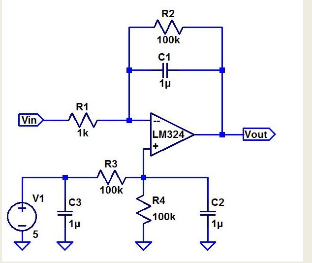
First we can assume that Vplus = 0, and add R2 and C1 in parallel and label it Z.
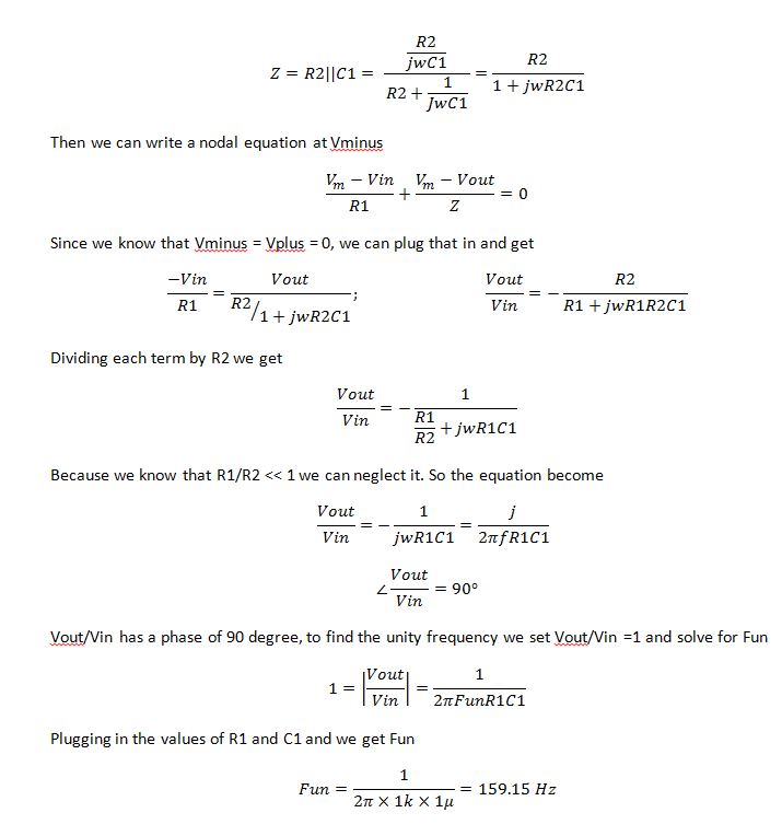
- What can you neglect to simplify the calculation?
Since we know that R2 >> R1 we can neglect it to simplify our calculation
- Does the circuit work if you remove the 100k? Why or why not?
Of
course the circuit still works if you remove the 100k. because we know
that R1/R2 goes to zero R2 is not significant in the frequency response
equation. - Does the 100k have much of an effect on the frequency response?
No as stated above. But having the 100k resistor will cause our output to have clipping effect at certain frequency.- Verify your calculations with experimental results.
- Show, at the unity-gain frequency of the integrator, that the input and the output have the same peak values.
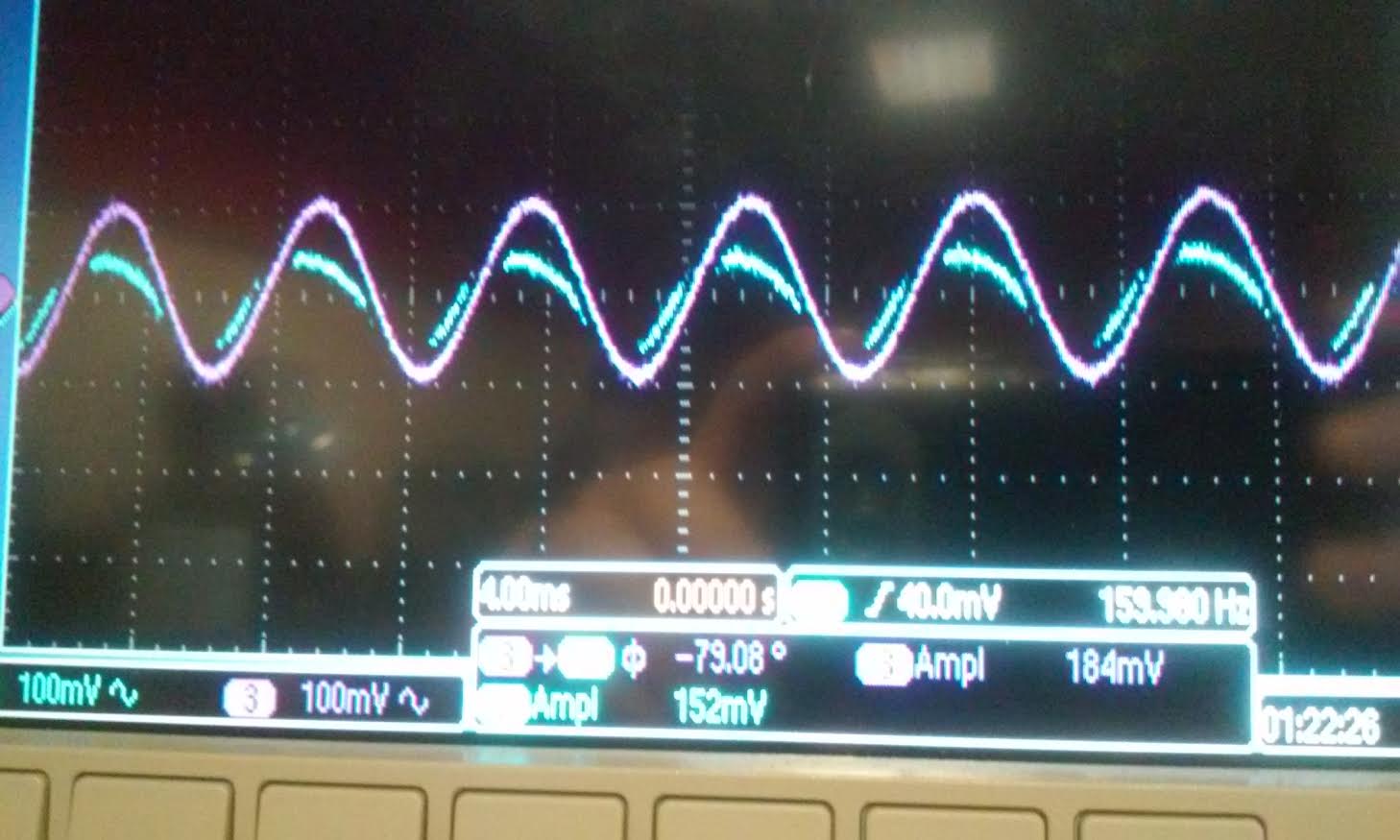
Below you see the image of two scope, one with the
100k R2 resistor, the other did not. As you can see both scope have
nearly the same amplitude and the same frequency. For scope 2 we put
the center at two different position to see the two graph easily,
otherwise one would be right on top of each other and you cannot
distinquish between the input and output. For scope1 we put the
position of the input and output the same and you can see that there is
some clipping going on there because of the huge resistor. The value of
resistor and capacitor we used was R1=1k, R2=100k, C1=1u. You can see
from both scope when the frequency is around 160Hz the input and output
have the same amplitude.
| With R2 | Without R2 |
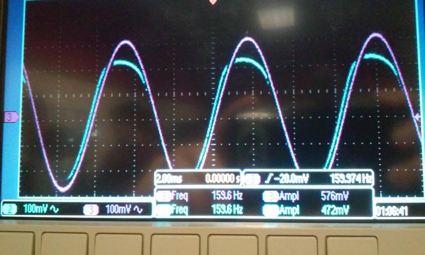 | 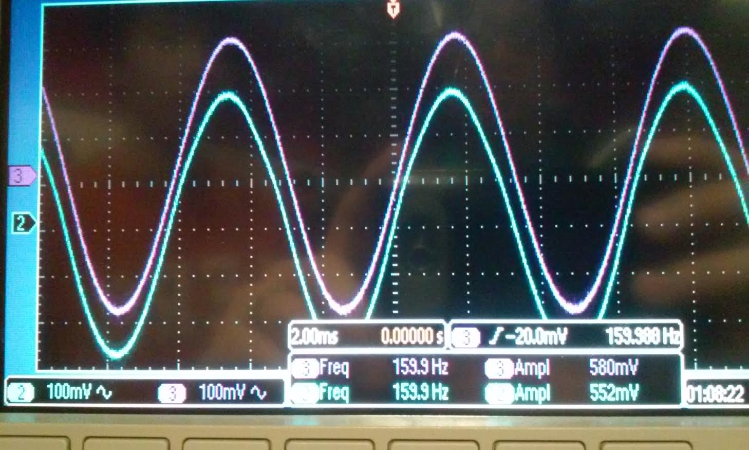 |
- Is the phase shift between the input and the output what you expect? Why or why not?
Below
is the scope reading of the phase shift it read -79 degree. Its reading
is negative because we measured phase from input-to-output not
output-to-input. the phase is lower than the expected value of 90
degree. Again the op-amp LM324 is not ideal and doing real world
application is different then simulation on a computer or hand
calculation. In the hand calculation and using LtSpice we can get the
phase difference to be exactly 90 degree and both the input and output
to be exactly the same value. But real world application each op-amp
and capacitor is different so we know that there is some minor
difference in the theoretical result vs. the experimental value but the
difference is small so we can say that the result we found in lab is
within the ballpark of our hand calculation. We calculated the phase
assuming R1/R2 =0 but for our circuit we included R2 so we can expect
that the phase will be a little different than the calculated value.
- Next, design, simulate, and build a square-wave to triangle wave generation circuit.
From
the video tutorial on Op-amp above we was able to design a circuit like
below with the square wave input that generated a triangle wave. As you
can see from the schematic VCM is 2.5 V. and the pulse is from 0 to 5V.
The waveform shows the input and output of the schematic.
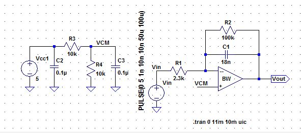
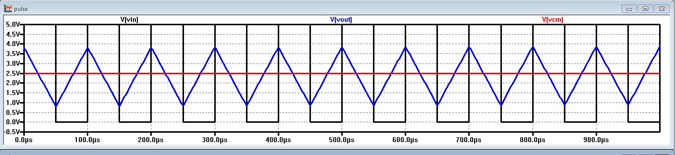
- Assume the input/output frequency is 10 kHz and the output ramp must swing from 1 to 4 V centered around 2.5 V.
- Show all calculations and discuss the trade-offs (capacitor and resistor values, input peak, min, and average, etc.)
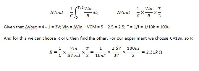
Conclusion: For
part 1, we our job was to calculate the unity frequency it was 160Hz.
We found that if R2 >>> R1 then it can be neglected in
calculating Fun. When we did our experiment we did one with the big
resistor connected to the circuit and one without it. Both scope look
exactly the same, the input and the output does not change with R2.
From the calculation we found that the pahse difference between the
output and input is 90 degree. While in lab we was only able to measure
it at 79 degree. For the second part, we was to design a circuit that
takes the square wave input from 0 to 5 V. The output was to center
around 2.5V and swing from 1V to 4V. We use the equation derived in the
lecture and found R=2.3k with our choose C=18n. As you can see from the
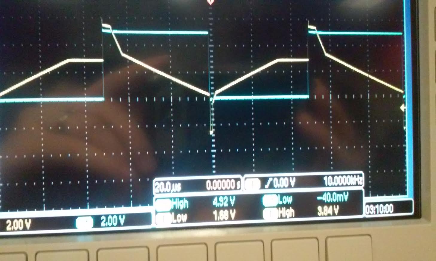
simulation and the actual experiment they varies greatly. From the
simulation we had our pulse input start from 0-5V.and set the period to 100u. The rise time, time one, fall time, and the delay determines the speed of our circuit you can see the value from the schematic. Our experiment was a little bit different than our simulation as you can see from the scope reading the input was from -40mV to 4.92 V, the scope gave us this reading even though our input was 0-5V. and our swing was from 1.88V to 3.84V.
Return to EE420L front page