EE 420L Engineering Electronics II Lab - Lab 4
Nha Tran
02/26/2015
NSHE: 2000590233
trann4@unlv.nevada.edu
Again, this lab will utilize the LM324 op-amp (LM324.pdf).
For the following questions and experiments assume VCC+ = +5V and VCC- = 0V.
- Estimate, using the datasheet, the bandwidths for non-inverting op-amp topologies having gains of 1, 5, and 10.

From
the data sheet of the LM324 Op-amp we can see that the unity gain
frequency is 1.3 MHz. The equation to find the Bandwidth (BW) is BW =
Fun/Aol, for the gain of 1, 5, and 10 we have the following Bandwidth.
| Gain | Bandwidth |
| 1 | 1.3 MHz |
| 5 | 260 kHz |
| 10 | 130 kHz |
- Experimentally verify these estimates assuming a common-mode voltage of 2.5 V.
- Your
report should provide schematics of the topologies you are using for
experimental verification along with scope pictures/results.
- Associated comments should include reasons for any differences between your estimates and experimental results.
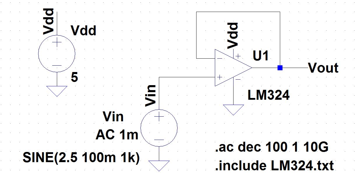
Since
we know the gain for the non-inverting topology is gain = 1 +(R2/R1) to
get a gain of 1 we build a circuit in lab similar to the one below
using ltspice.
non-inverting topology: Gain = 1
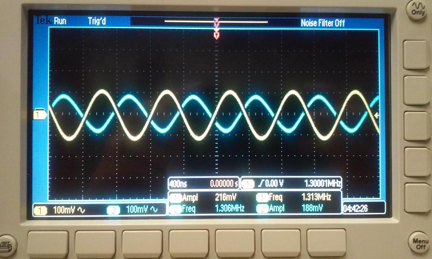
To get a gain of 1 we did not have any resistors;
we just put a
wire between Vout and Vminus, as you can see from the scope reading the
amplitude of the input is 216mV with a 100mV input from the signal
generator, and the output's amplitude was 188mV. The value of the input
and output is close enough that we can say that the gain is
approximately 1. Also from the scope
reading you can see that the input frequency is 1.3MHz. Bandwidth =
1.3MHz |
 |  |
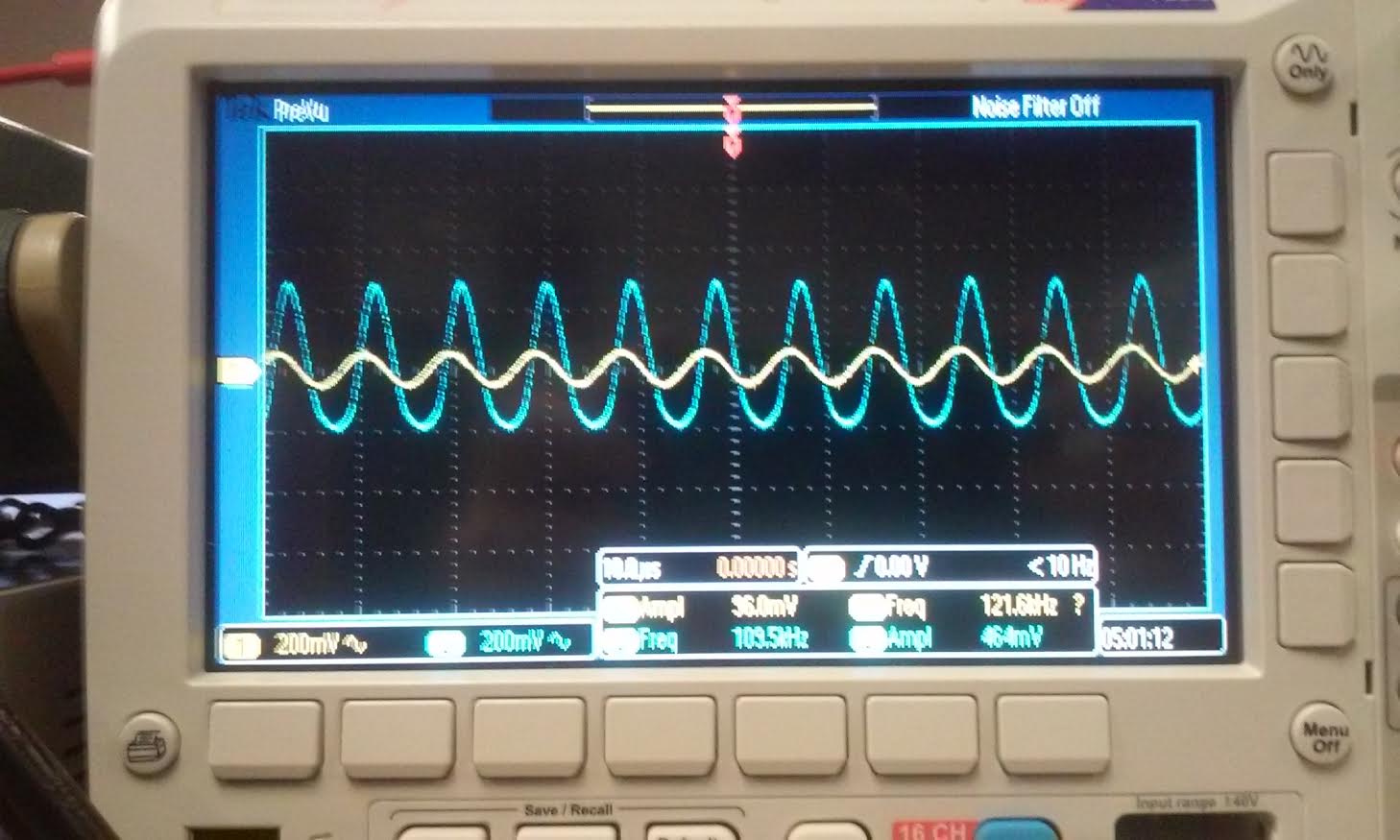
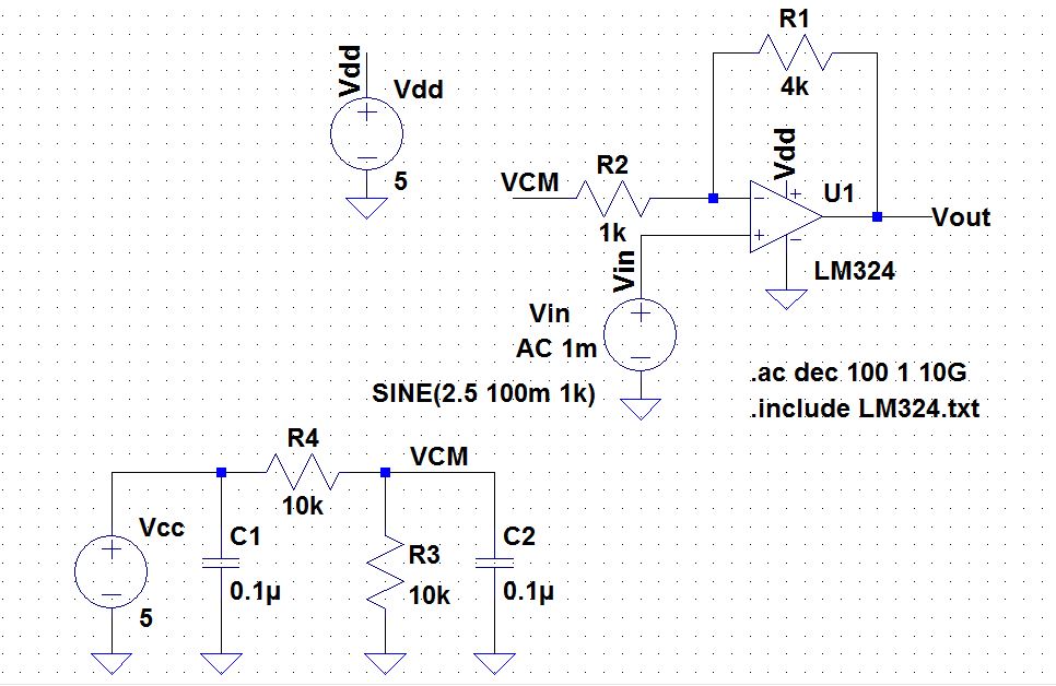
non-inverting topology: Gain = 5
For the gain of 5, we used the resistor of 4k and 1k since the equation
for gain is Aol=1+R2/R1. The input amplitude was 96 mV, while the
output was 464mV. The ratio is approximately 5, so we can say that the
gain is 5. Our input frequency was 110 kHz. Bandwidth = 110kHz |
 |  |
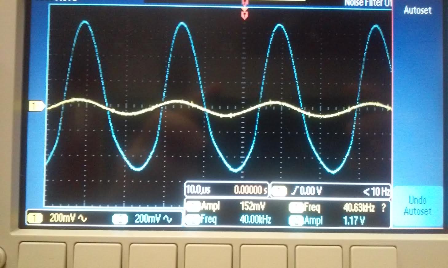
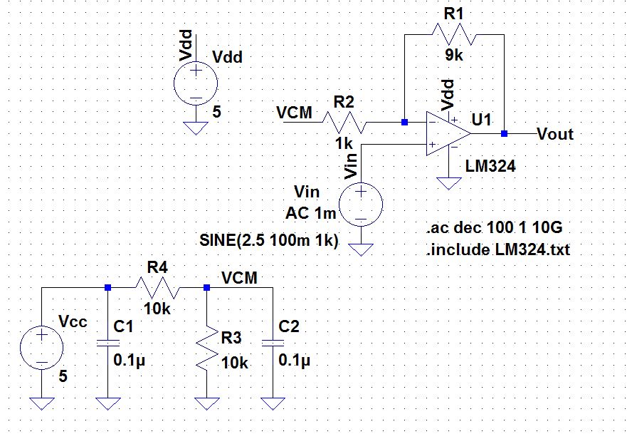
non-inverting topology: Gain = 10
For the gain of 10 we used a 9k and 1k resistor our input was 152mV, and the output was 1.17 V. The input frequency was 40kHz. Bandwidth = 40kHz |
 |  |
As you can see from the table below, the theoretical
bandwidth differs from the experimental bandwidth because from our
estimation of the theoretical value the Vcc input was 30V. However, for
the lab experiment we only used a 5V Vcc. The value that the datasheet
gives us is just a typical rating of GBP for all the op-amp that was
produced at the time. the datasheet gave us a 1.3MHz GBP, that value
was just a typical value but in reality it can varies. LM324 was design
for low power, they can get alot of unwanted noise and corssover
distortion from cicruits. Their frequency response and GBP is much less
when the VCC is less than 30V, which was the case in our lab. Also we
did not factor in the noise gain of the op-amp that we are using.
| Gain | Theoretical | Experimental |
| 1 | 1.3 MHz | 1.3 MHz |
| 5 | 260 kHz | 110 kHz |
| 10 | 130 kHz | 40 kHz |
- Repeat these steps using the inverting op-amp topology having gains of -1, -5, and -10.
The
gain for a inverting op-amp is Aol = -R2/R1. The unity frequency from
the datasheet is 1.3Mhz. the equation for BW = Fun/(1+Aol). The
theoretical bandwidth that we should get from the datasheet is
| Gain | Bandwidth |
| 1 | 650 kHz |
| 5 | 217 kHz |
| 10 | 118 kHz |
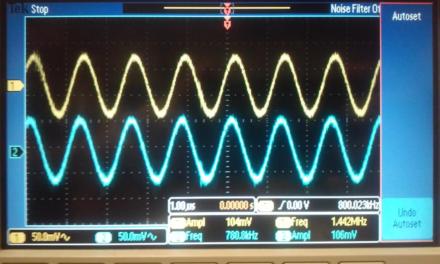
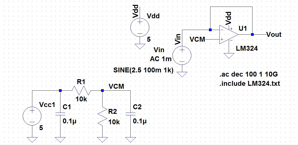
Inverting gain = 1:
similar to the non-inverting op-amp circuit except this
time we just have the signal goes to the Vminus and VCM goes to Vplus.
with our input of 104mV we got a 106mV output when the BW is 780kHz.
Again similar to the above schematic we did not use any resistor for a
gain of 1. |
 |  |
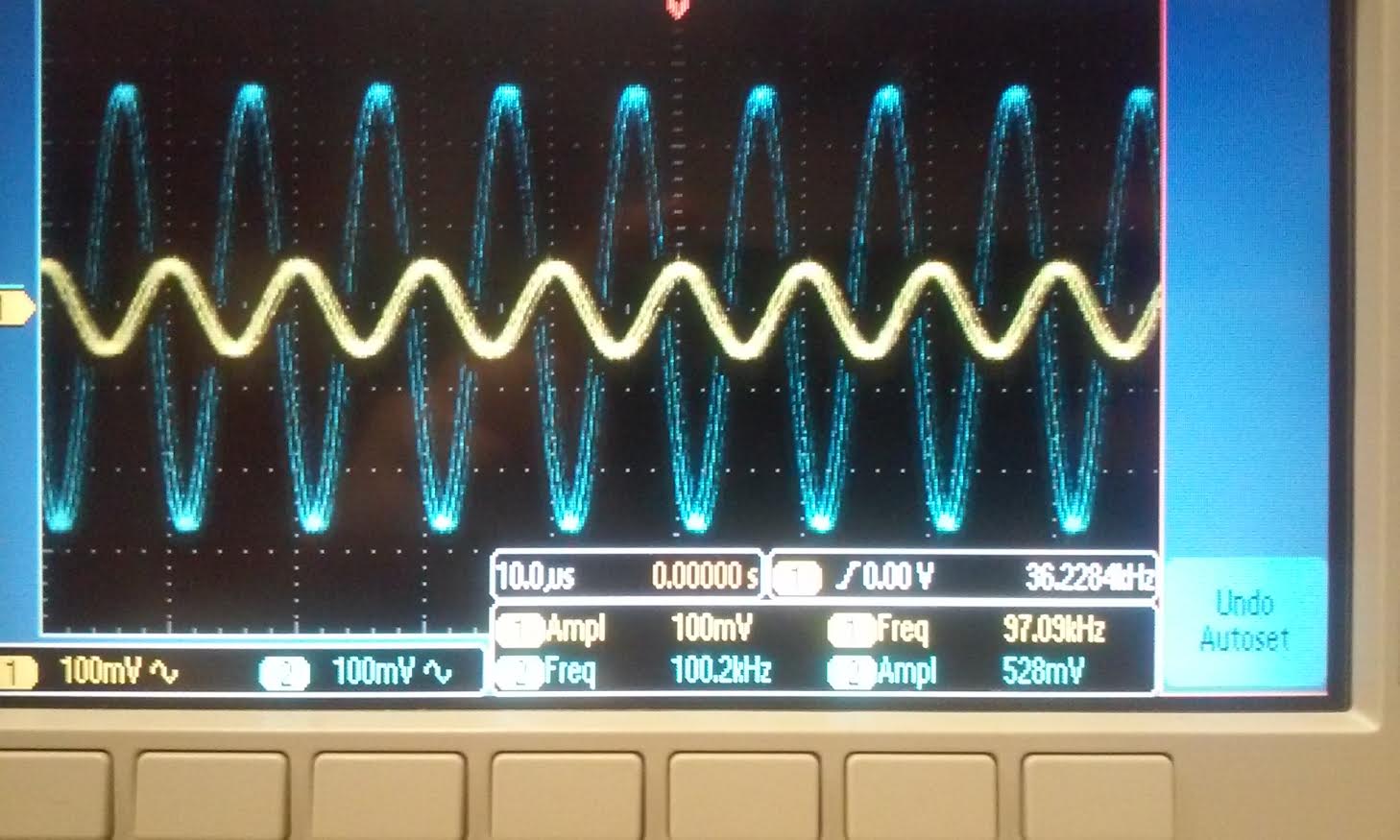
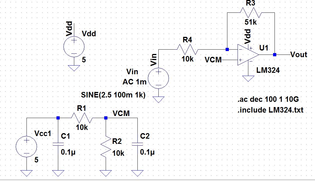
Inverting gain = 5:
This time our input was 100mV, the output was 528mV,
indicating that the gain is 5. the bandwidth that we were able to
achieve this was 100kHz. This time we used a 10k and 51k resistor for
our R1 and R2. |
 |  |
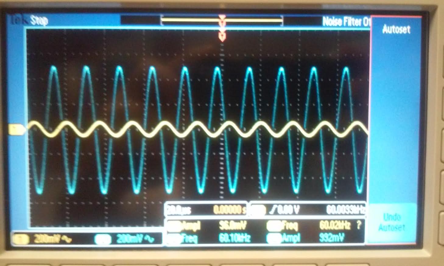
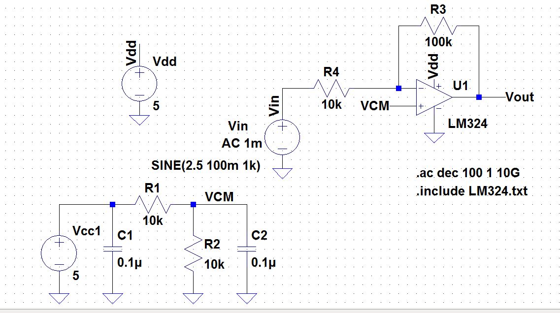
Inverting gain = 10:
For a gain of 10 we used a resistor of 10k and 100k, our
scope input was 96mV our output was 990 mV indicating a gain of 10.
This was achieved with the bandwidth of 60kHz. |
 |  |
As
you can see from the table below, the theoretical values differs from
the experimental values. The same explanation that i used for the
non-inverting op-amp above.
| Gain | Theoretical | Experimental |
| 1 | 650 kHz | 780 kHz |
| 5 | 217 kHz | 100 kHz |
| 10 | 118 kHz | 60 kHz |
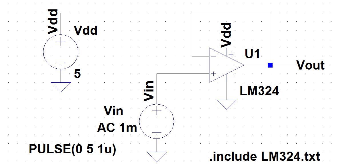
- Design
two circuits for measuring the slew-rate of the LM324. One circuit
should use a pulse input while the other should use a sinewave input.
- Provide comments to support your design decisions.
- Comment on any differences between your measurements and the datasheet’s specifications.

The
slewrate that the datasheet gives us is 0.4 V/us, again this is the
typical value it will probably not match our experimental value.
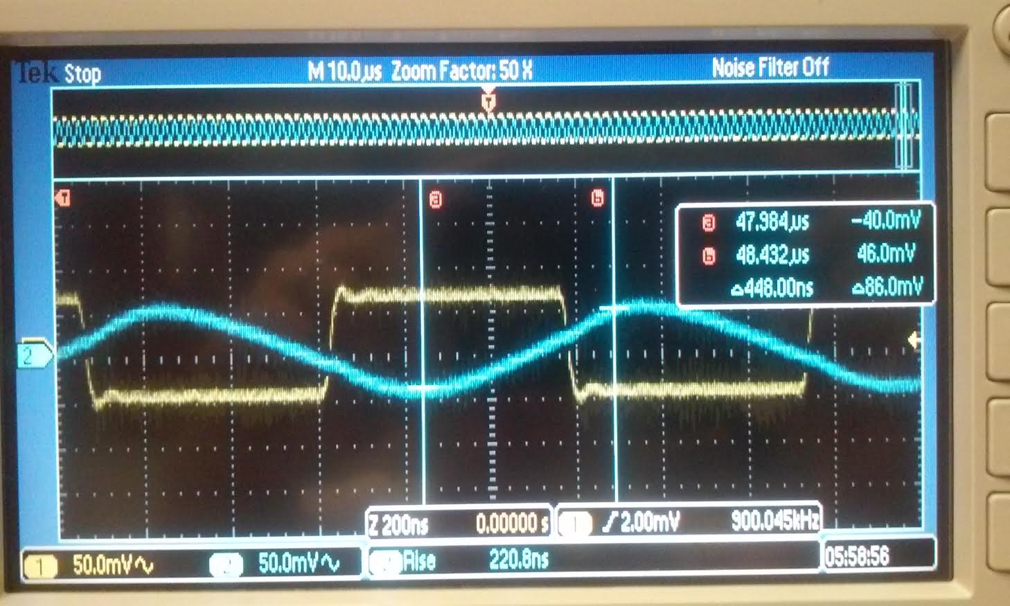
| For
the slewrate using a pulse wave we just choose the non-inverting
topology with no resistor value. We made a measure of the rise time
using the scope's measure option. And to measure the 10% and 90%
voltage we did an eyeball of the output. We adjust the cursor to the
location that we think was 10% and 90% respectively. As you can see
from the scope reading the rise time is 220.8 ns. and the deltaV =
86mV. We can use the equation slewrate (SR) = deltaV/RiseTime, for our
experiment the SR = 86mV/220.8ns = 389mV/us = 0.389V/us. |
 |  |
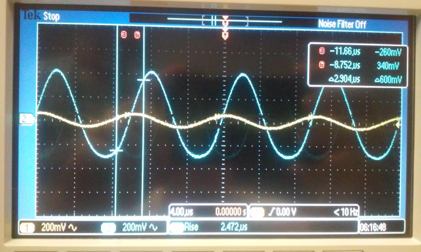
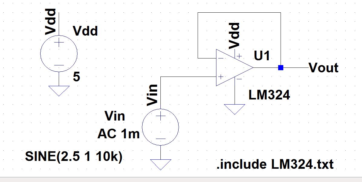
| For
the sine wave we use the same topology without any resistor also. we
made the same measurement and SR=600mV/2.472us = 243mV/us = 0.243V/us. |
 |  |
| Theortical | Pulse wave | Sine Wave |
| 0.4 V/us | 0.389 V/us | 0.243 V/us |
The
slewrate is the rate of change of the output voltage with time (dV/dt),
usually given as V/us. When we have an input of a square wave, the slew
rate is more accurate than the input of a sine wave because for the
square wave the output is able to keep up with the input. For a sine
wave, the output change at the same rate as the input so the slewrate
is unable to keep up. Therefore, for the sine wave input the slew rate
is much slower than the theoretical value. This can be analyse using
mathematic. SR = dV/dt. For a square wave; there is only one change, at
the corner of the rising edge and the peek, the change in voltage is
flat so it deriviative is faster to derive (it is a constant). But for
a sine wave, dV/dt changes at everypoint, thus the slewrate is slower.
Conclusion:
from this lab we can see that the unity frequency or GBP is equal
to the gain times the Bandwidth, (GBP = Aol * BW) so for a given
op-amp if we want a higher bandwidth then we need a lower gain, or vice
versa. If we want to design with a higher gain and a higher bandwidth
then we need an op-amp with a higher GBP. the difference between the
non-inverting topology vs. the inverting topology is that with the
non-inverting we get the higher bandwidth for a given op-amp. So if we
want to maximize our bandwidth then we need to choose the non-inverting
topology. However, this bandwidth difference between the two topology
becomes less significant when we raise the gain. We can analyse the
difference between the non-inverting vs the inverting by their BW
equation: for non-inverting BW=Fun/Aol, for inverting BW = Fun/(1+Aol).
so when Aol >> 1, then the two equation is the same.
Return to EE420L front page