EE 420L Engineering Electronics II Lab - Lab 3
Nha Tran
02/18/2015
NSHE: 2000590233
trann4@unlv.nevada.edu
Lab 03: Op-amps I, basic topologies, finite gain, and offset
This lab will utilize the LM324 op-amp (LM324.pdf).
Review the data sheet for this op-amp.
For the following questions and experiments assume VCC+ = +5V and VCC- = 0V.
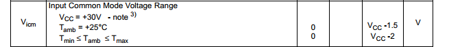
- Knowing
the non-inverting input, Vp, is at the same potential as the inverting
input, Vm, (called the common-mode voltage, VCM) what are the maximum
and minimum allowable common-mode voltages?
- Support your answer with an entry from the electrical characteristics table in the datasheet.
The
maximum allowable common-mode voltage according to the data sheet
LM324.pdf is Vcc-1.5 and Vcc-2. the minimum is Vcc-0. According to the
table below, LM324 will still operate under room temperature of 25
degree C and maximum Vcc input voltage is 32V and the minimum is 0V.
However, for our experiment our Vcc input is only 5V, therefore the
range of operation for our VCM is between 0-3.5V. VCM that is out of
this range will make the Op-amps inoperable.
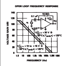
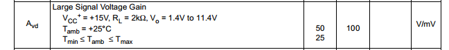
- What is a good estimate for the op-amp's open-loop gain?
- Support your answer with a plot from the datasheet and an entry from the electrical characteristics table.
From the graph and table below a good estimation for the open-loop gain is roughly around 100dB or 10000.
`
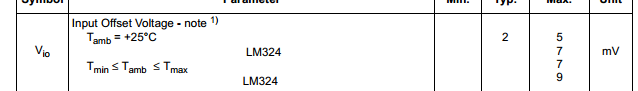
- What is a good estimate for the offset voltage?
- For worst case design what value would you use?
A
good estimation for the input offset voltage is 7mV. For worst case
scenerio we should use the maximum allowable which is 9mV.
Build,
and test, the following circuit. Note that a precise value for the 5k
resistors isn't important. You can use 4.7k or a 5.1k resistors.
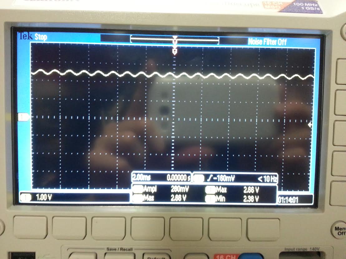
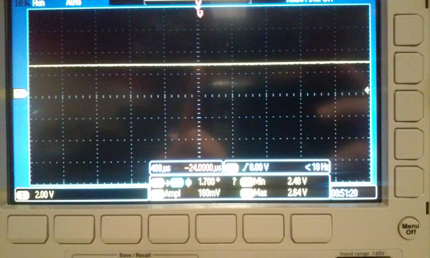
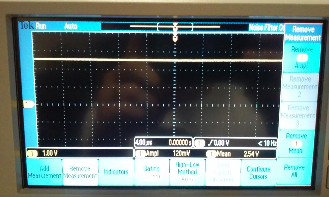
- What is the common-mode voltage, VCM? Does VCM change? Why or why not?
In
a analog signal circuit, a common-mode voltage VCM is half of the input
voltage, in our experiment VCC is 5V, therefore VCM should be 2.5V.
Ideally VCM does not change because VCC is getting divided by two 10k
Ohm resistors.VCM can only vary with VCC so as you increase VCC you
will also increase VCM. But in reality the resistor values is not
exactly 10k Ohm each so VCM can varies with the resistors values also. As
you can see from the scope below VCM is not exactly 2.5 V, in this case
the scope reads 2.54V.
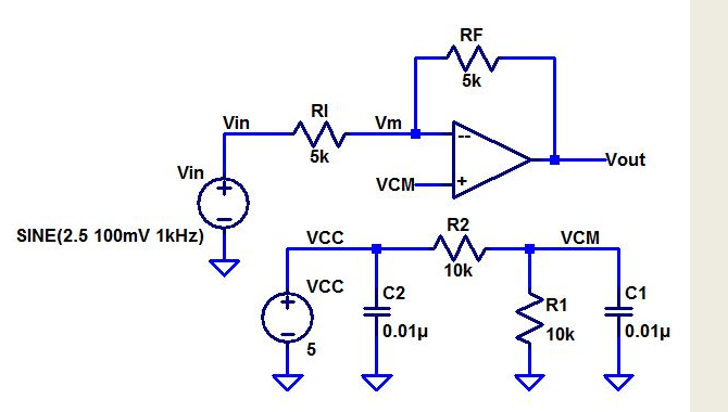
- What is the ideal closed-loop gain?
The ideal closed-loop gain is -RF/RI = -5k/5k = -1- What is the output swing and what is it centered around?
- What happens if the input isn't centered around around VCM, that is, 2.5 V?
- Provide a detailed discussion illustrating that you understand what is going on.
From
the picture below you can see that Vmin = 2.38V, Vmax = 2.66V. this
means that the output swings from 2.38V to 2.66V, and it centers around
2.54V. Ideally for this Op-amps the output swing is (plus minus) +-
100mV and centered around 2.5V. If the input is not centered around 2.5
then the output center voltage will do down when the input is higher
than 2.5. As you can see from the result below. Instead of having an
output swing from 2.4V to 2.6V. Our Swing is from 2.38V to 2.66V. The
image on the right is the Ac component of the output swing.
- What is the maximum allowable input signal amplitude? Why?

From
the data sheet we can see that the maximum input voltage is between
-0.3 to +32V. However, for our experiment with a 5V VCC, the maximum
VCM is 3.5V. Therefore, the maximum input amplitude is 3.5V - 2.5V =
1V. If Vin is centered around 2.5V and we add an AC input of 1V, this
will cause VCM to hit its maximum. If the input is higher than 3.5V
then the op-amps will go into triode and it will affect the open loop
gain and the output voltage.
- What is the maximum allowable input signal if the magnitude of the gain is increased to 10? Why?
If
the gain is increased by 10 then the input will be 1/10 of what it was.
This is because Vout = Aol(Vp - Vm), if everything is constant and Aol
is 10 then (Vp - Vm) = Vout/10. Which proves that Vin = 1/10 of its
original value if the gain is 10.
- What is the point of the 0.01 uF capacitors from VCC and VCM to ground?
- Are these values critical or could 0.1 uF, 1,000 pF, 1 uF, etc. capacitors be used?
A
capacitor connected from VCC and VCM to ground is called a decoupling
capacitor. Its purpose is to reduce the noise and make it stable. Its
value is not critical because capacitor do not affect DC voltage. - The data sheet shows that this op-amp has an input bias current that flows out of the op-amp's inputs of typically 20 nA.
- This current flows out of both the non-inverting and inverting inputs through the resistors connected to these inputs.
- Show how the operation of the circuit can be effected if, for example, R1 and R2, are much larger. Explain what is going on.
- What is the input offset current? What does this term describe?
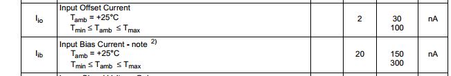
From
the table above the input offset current is between 30-100 nA. The
input offset current is the difference between the current going
through the positive and negative terminal of the op-amp. This value is
only taken into consideration when the two current are about the same
value. If both R1 and R2 is much larger than it would just slow down
the
circuit alot because it would take long time to charge the capacitor.
And if RF and RI was much bigger than the input current will be smaller
due to the big resistor.
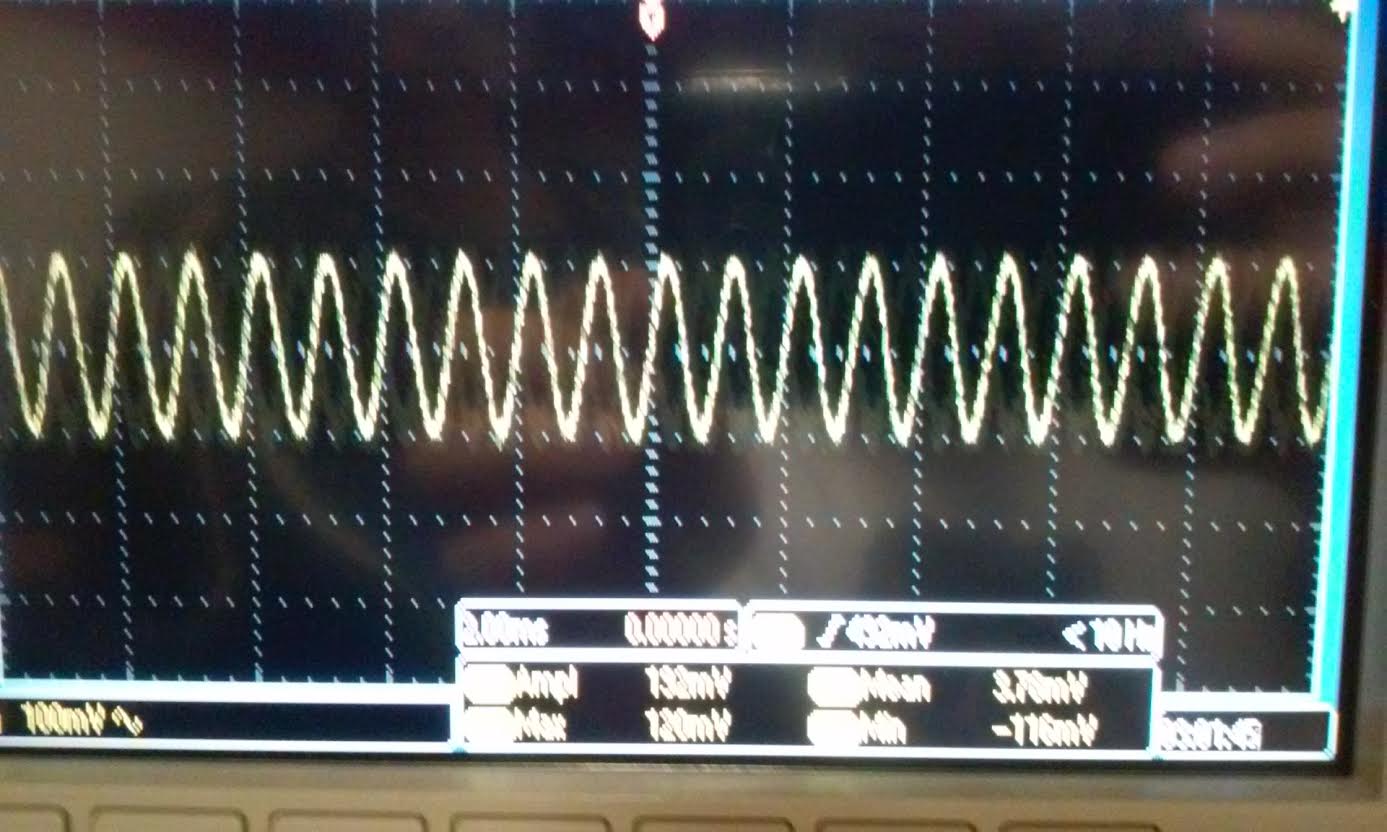
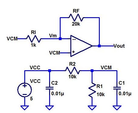
Explain how the following circuit can be used to measure the op-amp's offset voltage.
For
the following circuit below, VCM is connect to the positive terminal of
the Op-amps and also to the negative terminal with a 1k resistor. In
this case we have no AC input. so in order to measure the offset
voltage; using any simulation technique we can measure the Op-amp
offset voltage by taking a measurement of Vout and VCM. Then the offset
voltage is Vout-VCM. The
scope image to the right is the reading for the LM324 op-amp simulated
with the circuit below. You can see that without the 100mV AC running
through it the offset voltage is now differ by +- 100mV as compared to
the simulation above.
- Note that if the output voltage is precisely the same as VCM then the op-amp has no offset voltage (this is very possible).
- To measure small offset voltages increase the gain by increasing RF to 100k or larger. Explain what is going on.
When
the op-amp have a small offset voltage that the scope cannot detect, we
can change the value of RF to bigger. This will cause the close-loop
gain to increase and negate the output saturation level. Introducing a
big resistor to RF to measure the offset voltage is wise because the
offset biased current is usually in the nano-amps range so without a
big resistor you wont be able to get a good reading of the offset
voltage.
- Measure the offset voltage of 4 different op-amps and compare them.
LM339N
| RF = 20k, RI = 1k |
| Multi-Meter Reading | Oscilloscope Reading |
| VCM | 2.5217 V | 2.52 V |
| Vout | 2.4969 V | 2.50 V |
| Offset Voltage | 24.8 mV | 20 mV |
LM348
| RF = 1k, RI = 1k | 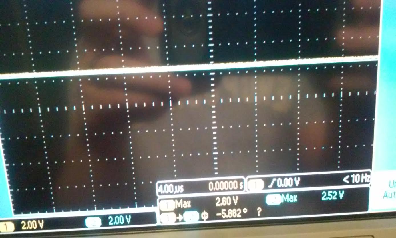 |
| Multi-Meter Reading | Oscilloscope Reading |
| VCM | 2.5283 V | 2.52 V |
| Vout | 2.6187 V | 2.60 V |
| Offset Voltage | 90.4 mV | 80 mV |
| RF = 100k, RI = 1k | 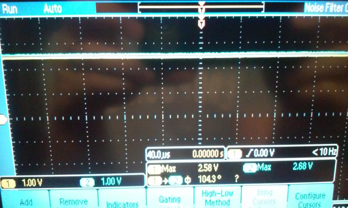 |
| Multi-Meter Reading | Oscilloscope Reading |
| VCM | 2.5283 V | 2.58 V |
| Vout | 2.6585 V | 2.68 V |
| Offset Voltage | 130.2 mV | 100 mV |
UA741CP (Vin = 5.2V)
| RF = 20k, RI = 1k | 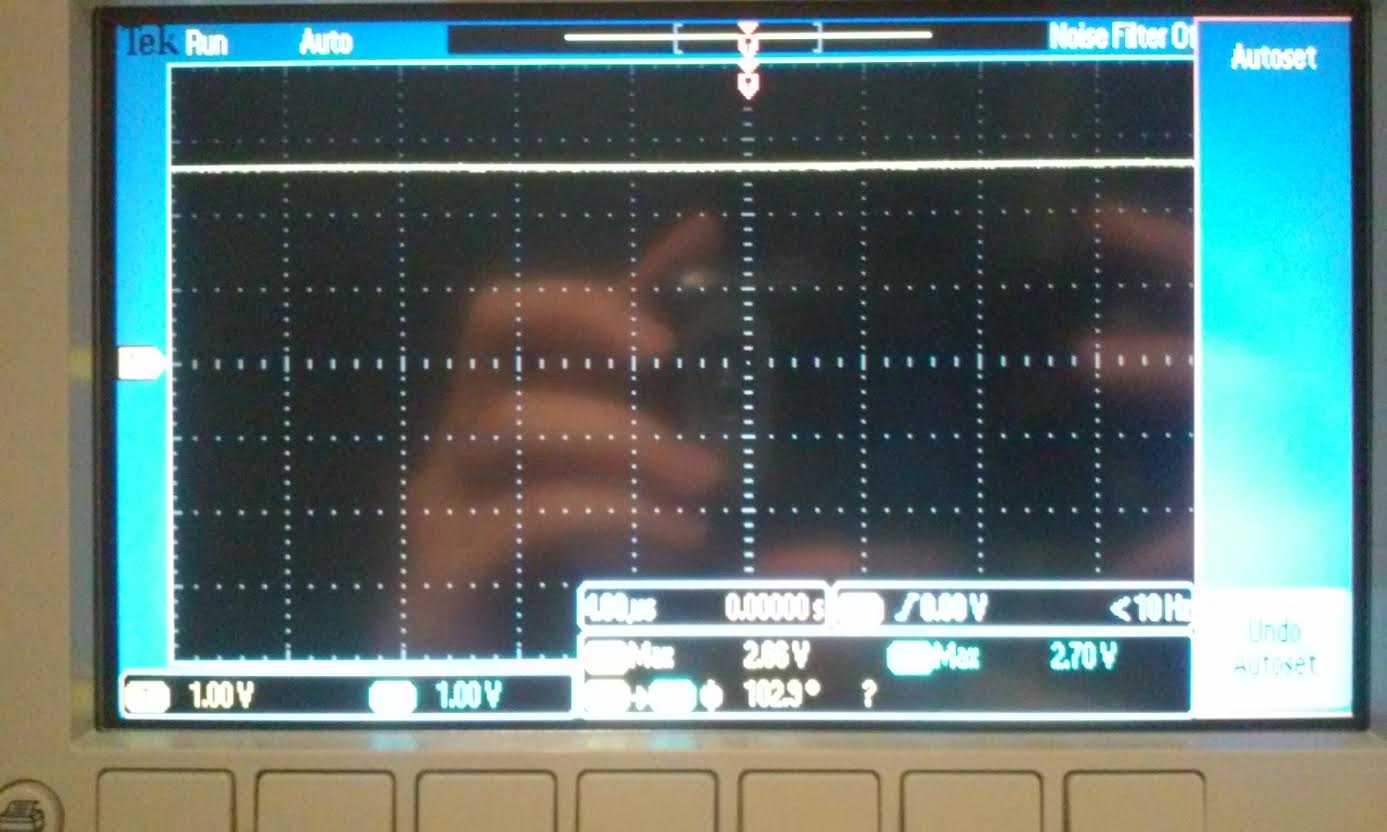 |
| VCM | 2.66 V |
| Vout | 2.70 V |
| Offset Voltage | 40 mV |
| RF = 100k, RI = 1k |  |
| VCM | 2.66 V |
| Vout | 2.86 V |
| Offset Voltage | 200 mV |
TL081CP
| RF = 30MEG, RI = 1k, Input Voltage = 15.3V | 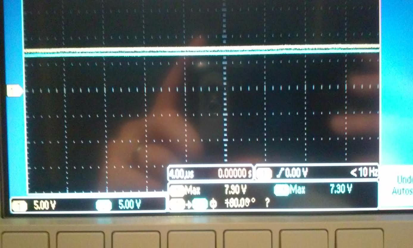 |
| VCM | 7.90 V |
| Vout | 7.30 V |
| Offset Voltage | 600 mV |
well
first lets clarify that some offset voltage was so small that measuring
with the oscilloscope was impossibe to get a good accurate reading
because it only have a 2 digit accuracy, while the multi-meter had a 4
digit accuracy. So therefore, some of our data we used the multi-meter
reading along with the oscillope reading to show the accuracy
difference. As you can see from the tables above, each op-amp have
different offset voltage and they can vary with varying RF. This was
demostrated with LM348. For this op-amp we used two difference RF
values and noticed that when you increased RF you also increase the
offset voltage of the op-amp. This was also the case with UA741CP. For
the last op-amp (TL081CP) the value that the datasheet gave us
was so small that putting a 100k resistor for RF gave us a zero reading
for the offset voltage. So we had to find the biggest resistor in lab
which is 30M we also raised the input voltage higher so that the scope
would give us a voltage difference between VCM and Vout.
Return to EE420L front page