EE 420L Engineering Electronics II Lab - Lab 2
Nha Tran
02/05/2015
NSHE: 2000590233
trann4@unlv.nevada.edu
Lab 02 Operation of a compensated scope probe
Perform, and document in your html lab report, the following:- Show scope waveforms of a 10:1 probe undercompensated, overcompensated, and compensated correctly.
- Comment
on where the type of scope probe (i.e., 1:1, 10:1, 100:1, etc.) is set
on your scope (some scopes detect the type of probe used automatically).
- Draft
the schematic of a 10:1 scope probe showing: the 9 MEG resistor, 1 MEG
scope input resistance, capacitance of the cable, scope input
capacitance, and capacitance in the probe tip.
- Using
circuit analysis, and reasonable/correct values for the capacitances,
show using circuit analysis and alegbra (no approximations), that the
voltage on the input of the scope is 0.1 the voltage on the probe tip.
- Devise
an experiment, using a scope, pulse generator, and a resistor, to
measure the capacitance of a length of cable. Compare your measurement
results to the value you obtain with a capacitance meter. Make sure you
show your hand calculations.
- Build a voltage divider using two
100k resistors. Apply a 0 to 1 V pulse at 1 MHz to the divider's input.
Measure, and show in your report, the output of the divider when
probing with a cable (having a length greater than or equal to 3 ft)
and then a compensated scope probe. Discuss and explain the differences.
- Finally,
briefly discuss how you would implement a test point on a printed
circuit board so that a known length of cable could be connected
directly to the board and not load the circuitry on the board.
Ensure
that your html lab report includes your name, the date, and your email
address at the beginning of the report (the top of the webpage).
When finished backup your work.
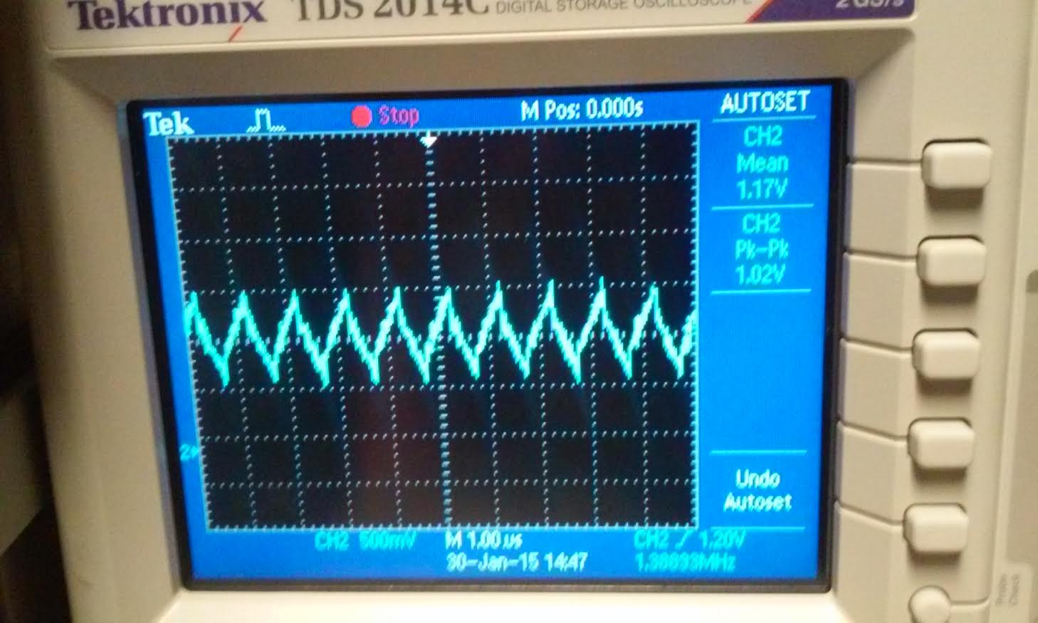
1) Show scope waveforms of a 10:1 probe undercompensated, overcompensated, and compensated correctly.
| undercompensated | overcompensated | compensated |
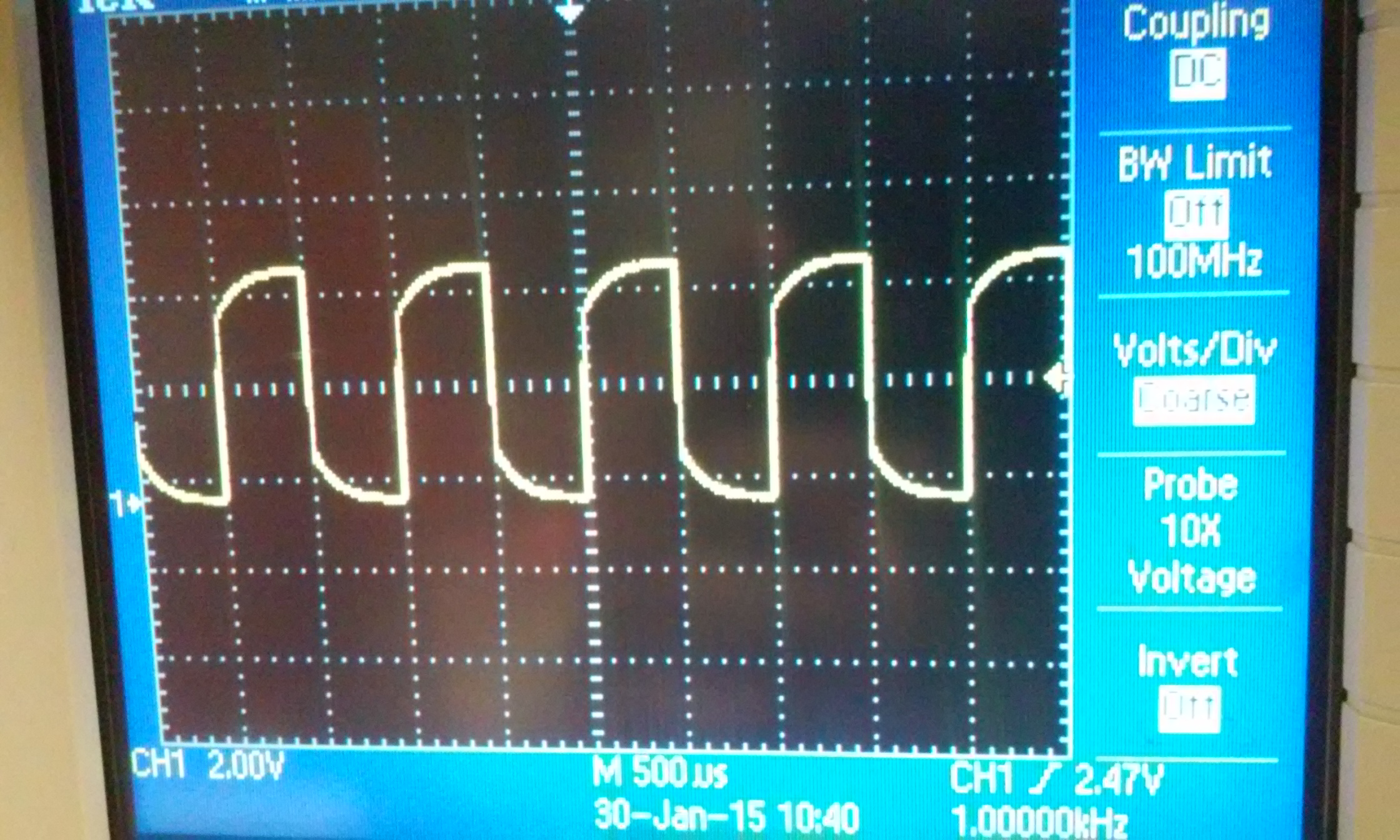 | 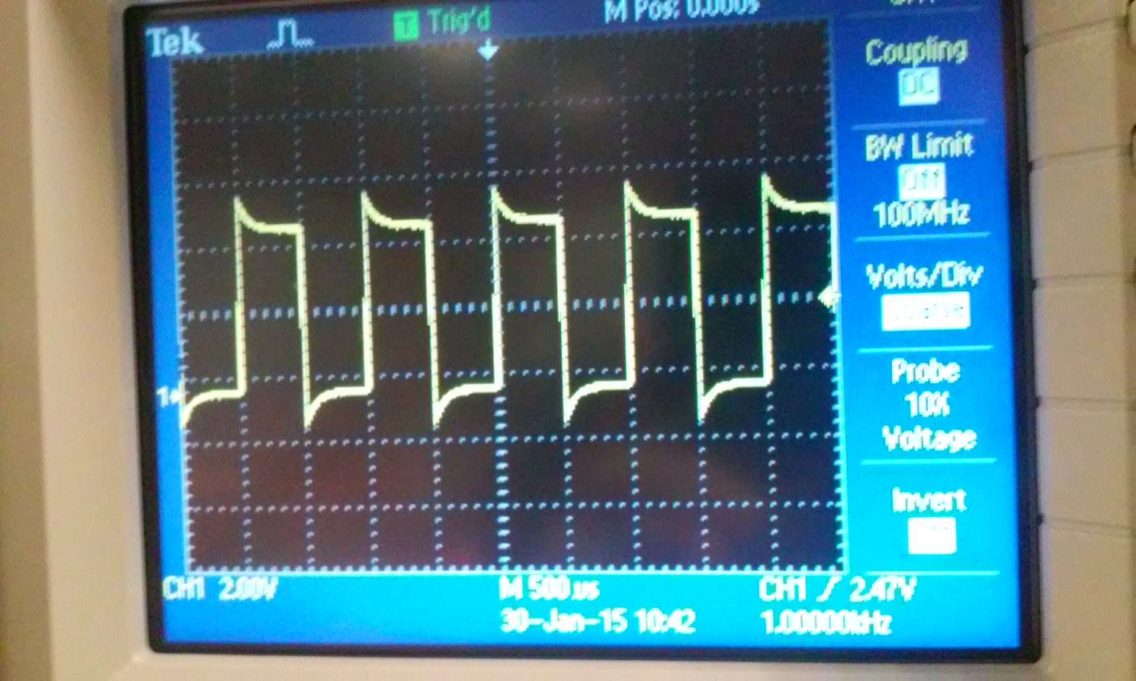 | 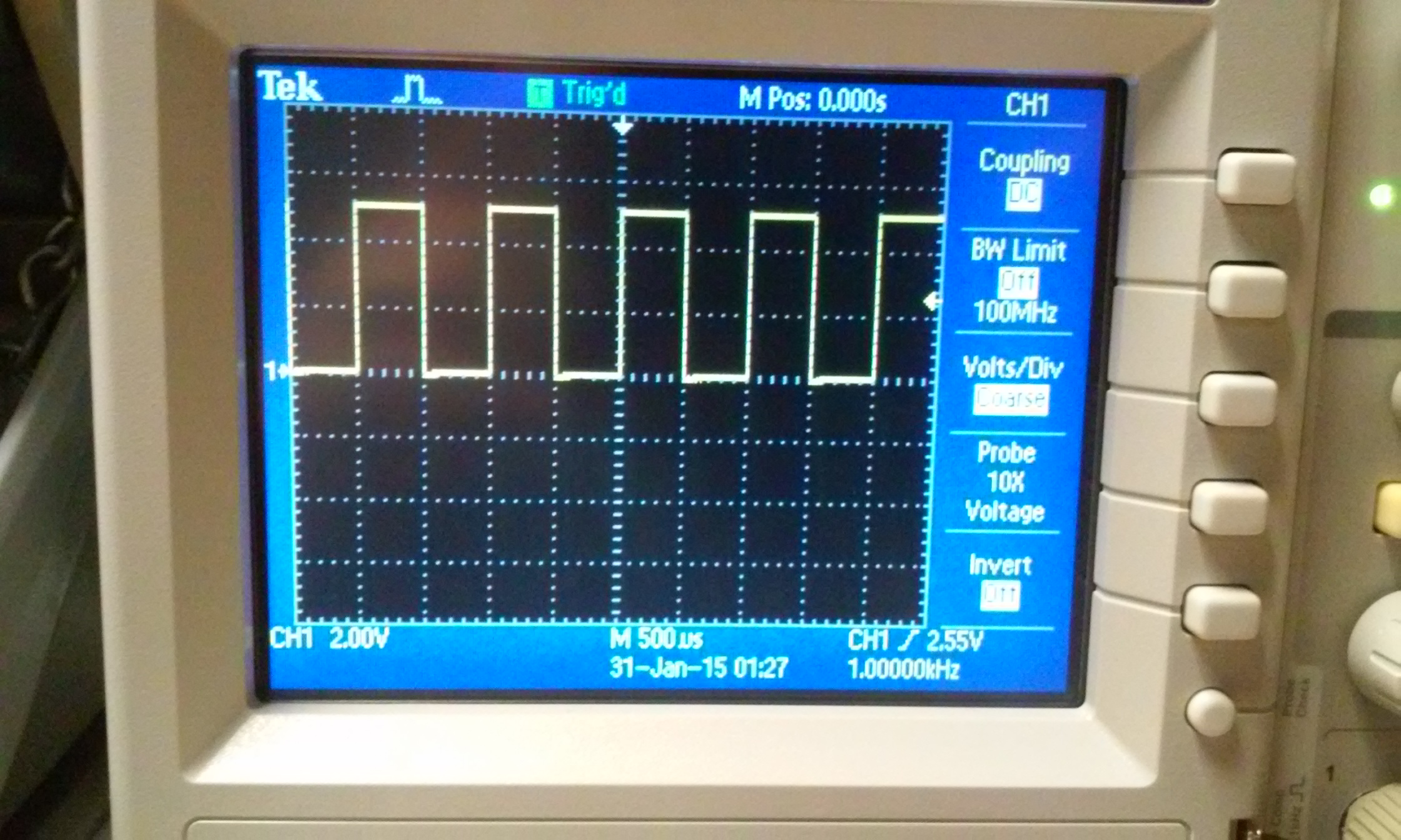 |
2) Comment
on where the type of scope probe (i.e., 1:1, 10:1, 100:1, etc.) is set
on your scope (some scopes detect the type of probe used automatically).
The
Probe that we used was already set at 10X. There was no options to
change it to 1X or 10X. From the table above you can see that all the
probe is automatically set to 10X. And from the image below it is also
at 10X.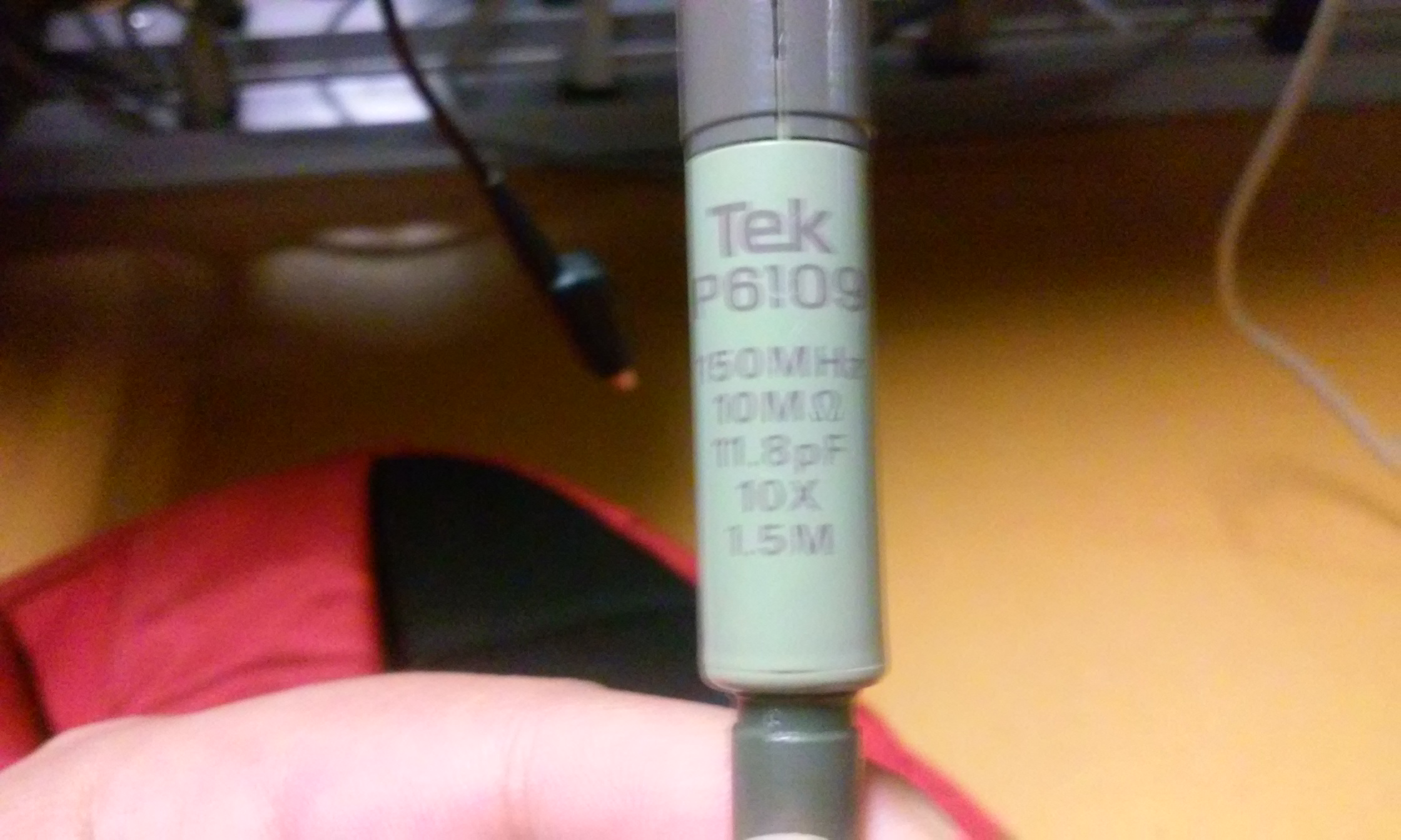
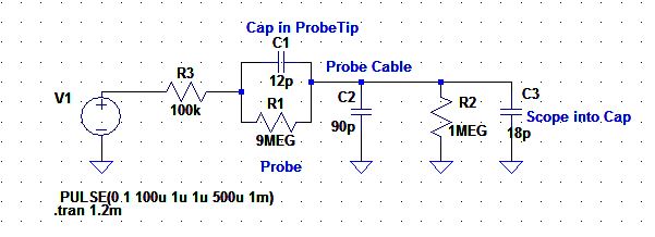
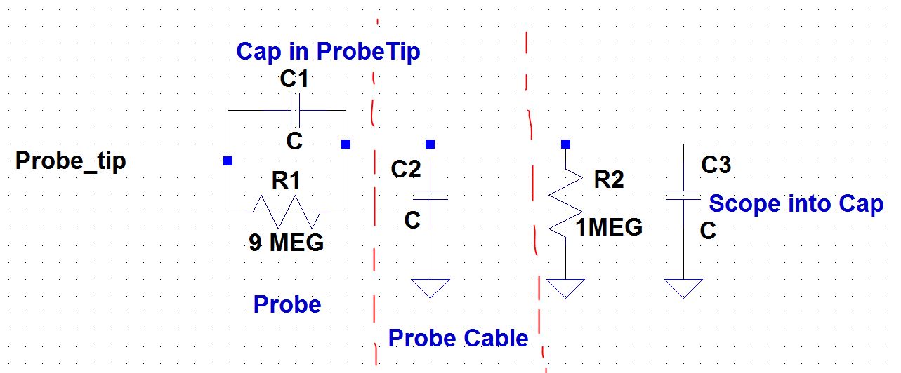
3) Draft
the schematic of a 10:1 scope probe showing: the 9 MEG resistor, 1 MEG
scope input resistance, capacitance of the cable, scope input
capacitance, and capacitance in the probe tip.
below is a schematic of the 10:1 probe scope.
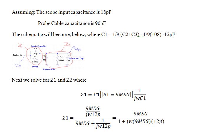
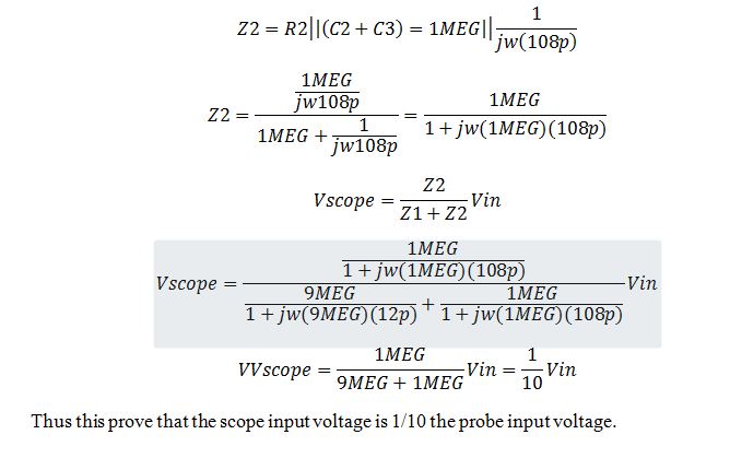
4) Using
circuit analysis, and reasonable/correct values for the capacitances,
show using circuit analysis and alegbra (no approximations), that the
voltage on the input of the scope is 0.1 the voltage on the probe tip.
5) Devise
an experiment, using a scope, pulse generator, and a resistor, to
measure the capacitance of a length of cable. Compare your measurement
results to the value you obtain with a capacitance meter. Make sure you
show your hand calculations.
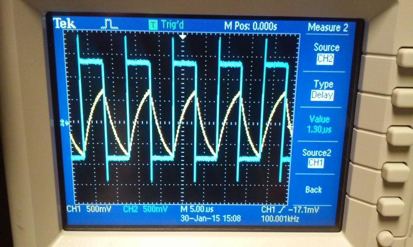
We
devise an experiment with a simple RC circuit with the input being a
pulse wave. We use a resistor value of 100k and the length of the probe
as our capacitor. and used the scope to measure its time delay. then we
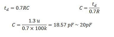
use the equation td = 0.7RC. With the probe reading of 1.30
us.
With
the hand calculation using time delay we were able to aproximate the
capacitance value to ~20pF. Next we went to TBE311L and measure the
cables capacitance with the capacitance meter and it gave us a reading
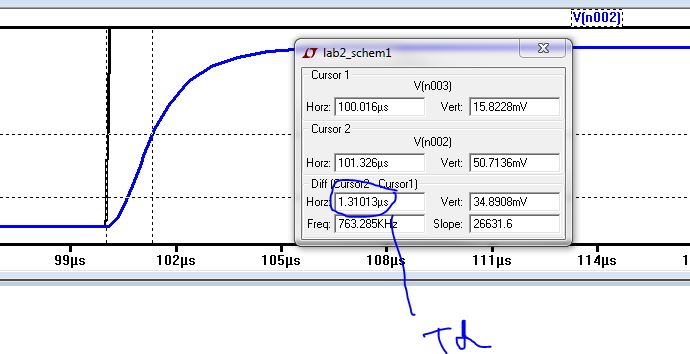
of 50pF. Next I used LtSpice with the input to simulate the
experimental circuit to verify that the time delay of the 100k resistor
and probe was actually ~1.3 us. And the time delay reading from the
simulation is 1.31 us.
6) Build a voltage divider using two
100k resistors. Apply a 0 to 1 V pulse at 1 MHz to the divider's input.
Measure, and show in your report, the output of the divider when
probing with a cable (having a length greater than or equal to 3 ft)
and then a compensated scope probe. Discuss and explain the differences.
Below are two picture one taken with a straight cable and one with the compensated probe. the scope probe was needed to obtain a reasonable output voltage compared to the straight cable. Without
the probe to measure the output, the signal charges and discharge
too quickly which causes the reading to be inaccurate.
| straight cable | compensated probe |
 | 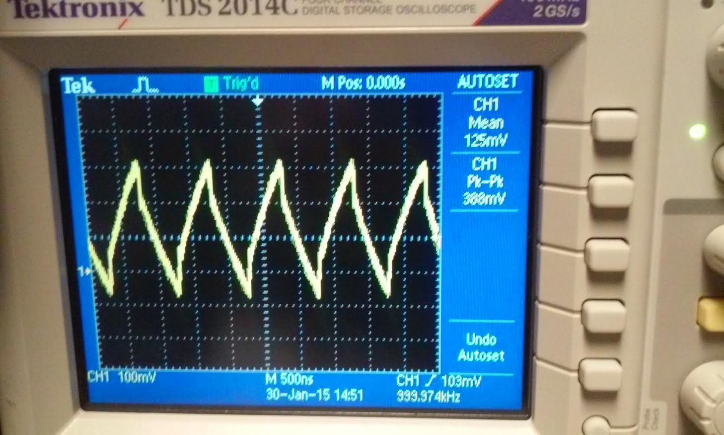 |
7) Finally,
briefly discuss how you would implement a test point on a printed
circuit board so that a known length of cable could be connected
directly to the board and not load the circuitry on the board.
To
implement a test point a on printed circuit board we can add a resistor
and capacitor in parallel before connecting the cables.
Return to EE420L front page